


Servicios Personalizados
Revista

Articulo
 Inglés (pdf)
 Articulo en XML
 Referencias del artículo
 Enviar articulo por email
Indicadores
-
 Citado por SciELO
Links relacionados
-
 Similares en
SciELO
Similares en
SciELO
Compartir

 Permalink
Acta Odontológica Latinoamericana
versión On-line ISSN 1852-4834
Acta odontol. latinoam. vol.27 no.2 Buenos Aires set. 2014
ARTÍCULOS ORIGINALES
Variations in the vestibular cortical bone of permanent canine teeth in orthodontic patients. a comparative study: linear tomography vs. cbct (3d accuitomo)
María E. Mateu, M.E. Martínez, H. Dagum, Sandra C. Benítez Rogé, Gabriela I. Bruno, Pedro Hecht, Alejandra A. Folco
Department of Orthodontics, School of Dentistry, University of Buenos Aires, Argentina
CORRESPONDENCE Dr Alejandra A.Folco Ramon Castro 2128, Olivos, CP: 1636 Pcia de Buenos Aires, Argentina e-mail: ale.folco@hotmail.com
ABSTRACT
The aim of this study was to compare the results of measuring the height of the vestibular cortical bone of canine teeth by linear tomography (LT) and 3-D Accuitomo cone beam computed tomography (CBCT) before and after aligning dental arches by orthodontic treatment. LT and CBCT were performed before and after orthodontic alignment on 12 canines in three patients undergoing orthodontic treatment, and the height of the canine vestibular cortical bones measured in mm. Measurements were taken by double-blinded operators. The mean variation in height of the vestibular cortical bone with orthodontic treatment was - 0,33 mm} 0.233 standard error using CBCT and -0,08mm } 0.55 standard error using LT. Analysis of variance (ANOVA) was performed to compare the techniques, the patients and upper and lower canines. No significant difference was found for any of the cases. Using LT to evaluate vestibular crest cortical bone in canines is comparable in efficiency to using CBCT. Height in millimeters is less in LT because image resolution is lower and when it is very thin it is not appreciable by this method.
Key words: Tomography; Cone-beam computed tomography; Orthodontics.
RESUMEN
Variaciones en el hueso cortical vestibular del canino permanente de pacientes ortodóncicos. estudio comparativo: tomografía lineal vs. cbct (3d accuitomo)
La finalidad del presente trabajo fue comparar los resultados de la medicion de la altura de la cortical vestibular de caninos, por tomografia lineal (TL) y tomografia computada de haz conico,3D Accuitomo (CBCT, cone beam computed tomography) antes y despues de alinear ortodoncicamente las arcadas dentarias. Se realizaron TL y CBCT pre y post alineacion ortodoncica de 12 caninos, correspondientes a tres pacientes en tratamiento ortodoncico y se midio en mm la altura de las corticales oseas vestibulares de los caninos. Las medidas fueron tomadas por dos operadores a doble ciego. La variacion de la altura promedio de la cortical vestibular con el tratamiento ortodoncico utilizando CBCT fue de -0,33 mm } 0.233 de error standard y con TL de -0,08mm } 0.55 de error standard. Se realizo Analisis de varianza (ANOVA) comparando las tecnicas, los pacientes y los caninos superiores e inferiores, sin encontrarse diferencia estadisticamente significativa en ninguno de los casos. La evaluacion de la cortical de la cresta vestibular de caninos utilizando TL es un metodo comparable en eficiencia a la CBCT. La medida de la altura en milimetros es menor en la TL debido a que la resolucion de las imagenes es menor y no es apreciable por este metodo cuando esta es extremadamente delgada.
Palabras clave: Tomografia; Tomografia computada de haz conico; Ortodoncia.
INTRODUCTION
Measuring the height of the vestibular alveolar crest of teeth provides very useful information for assessing whether it thins during orthodontic treatment. Thinned cortical bone generates an unfavorable crown-to-root ratio when masticatory forces are generated, and may produce injurious forces on the dental support structures. As canines are fundamental in lateral disocclusion and responsible for supporting all contact during that time, it is very important to preserve their cortical bone1. Intraoral and panoramic radiographs provide two-dimensional (2D) images which have been widely used in the past decade; nevertheless, it is difficult to distinguish structures in them because images of bone and tooth structures overlap2. Structures such as the mandibular canal, anterior nasopalatine canal or lingual foramen can be seen easily, but the disadvantage is that these images do not show the vestibular, lingual or palatal cortical bones or allow the width of the alveolar crest to be determined.2-6. In response to this limitation, other diagnostic methods have been developed such as LT, and more recently, CBCT, which provide cross sectional images of the maxillae with different degrees of resolution7. Panoramic equipment is used for LTs. Cross-sectional images are used for determining the placement of dental implants8, 9. The limitation of this type of image is the flow or blur, which necessitates considerable time for interpretation, which must be done by a trained professional9. In addition, the patient must keep still during tomographic acquisition of the image (about 20 seconds per zone)9, which may be uncomfortable or difficult for some patients. Measurements must be taken directly on the radiographs with a graduated ruler, using constant magnification. The methodological error for this technique is considered to be 0.5mm, which means that values with variations within this range should be considered similar.
Cone beam computed tomography uses a radiation cone which only rotates once around the patient to obtain the volumetric data for the region of interest10. The images obtained are reconstructed using an algorithm that produces high-resolution 3D images with a low radiation dose compared to axial computed tomography11-13. The advantages of this new equipment include: easy viewing and interpretation of the image, image limited to the site of interest, accuracy in bone dimensions and densities, excellent resolution, compatible software for positioning implants, small scanner size and scanner can be used on claustrophobic patients. Its main disadvantage is usually its limited availability due to the high cost of the equipment and studies performed with it. Moreover, the quality of the image depends on the field of view (FOV) - the greater the FOV, the lower the resolution11.
Absorbed dose is a magnitude used in Radiology and Radiological Protection to measure the amount of ionizing radiation received by a tissue or a living organism. The unit is the gray. Equivalent dose is a physical magnitude which describes the relative effect of the different types of ionizing radiations on living tissues. The unit is the sievert. Equivalent dose has greater biological significance than absorbed dose. Absorbed dose in grays is an adequate starting point for determining damage caused by radiation, but in biological organisms we are interested both in total energy deposited and in the effect it produces on living cells. To quantify this effect, we need a parameter that relates the dose to the biological consequences it produces. The quality factors used to define a biological equivalent dose of radiation are important. The biological equivalent radiation dose is a dose which is proportional to the biological effect of the radiation energy absorbed. In a digital panoramic radiograph is 13.3μSv.14 The equivalent dose in CBCT studies may be 4 to 78 times higher than LT studies, and 7 times lower than in multislice computed tomography (MSCT)15. There is a wide range of equivalent doses, depending on the type of study performed and the aperture of the window selected. The dose ranges from 68 to 560 μSv per slice in CBCTs using an average FOV, and from 69 to 1073 μSv using a large FOV, while in MSCT with a similar window, the equivalent does is about 860μSv16,17.
Vestibular cortical bone may undergo variations when teeth are aligned on the arch, particularly when there is lack of space or crowding. These changes should be evaluated over the course of orthodontic treatment. Nevertheless, no quantitative evaluation of these variations was found in the literature. A CT scan is a useful and efficient method, but too costly for measuring a large number of patients. LT provides information about the height of the cortical in canines more economically. Our hypothesis is that LT provides results comparable to those obtained through CBCT, and that LT may be used to evaluate variations in the canine cortical bone during orthodontic treatment. This paper compares the results obtained by CBCT and LT in evaluating the vestibular cortical bone in patients undergoing orthodontic treatment.
MATERIALS AND METHODS
We compared 12 pre-treatment to 12 post-treatment measurements of alignment, in 3 patients aged 15 to 35 years, who had completed the alignment stage in their orthodontic treatment using self-ligating braces and Ni-Ti-Cu arches (Damon system). Participating patients signed informed consent.
This study was performed using a LT scanner (Proscan, Helsinsky Planmeca, Finland) and a cone beam CT scanner (Accuitomo Morita, Japan). CT slices were made of the 4 canines (2 upper and 2 lower) in each patient at the beginning and end of the alignment stage. Apex-crest distance was measured by LT and CBCT, as shown in Fig. 1. Measurements were taken along a line parallel to the tooth axis from the vestibular crest cortical bone to the level of the root apex. The arch was considered to be aligned when it was able to receive the rectangular arch. The resolution of the LT enables discrimination as from a minimum of 0.5 mm, so values with differences within that range are considered similar for this technique. The difference in height of the cortical bones before and after alignment was measured in mm and the LT and CBCT results were compared. The measurements were taken independently by two calibrated, double-blinded operators (Fig. 1).
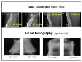
Fig.1: Measurements on CT slices. The measurements were made by drawing a line parallel to the longitudinal axis of the tooth from the vestibular crest to the apex.
RESULTS
According to descriptive statistics, considering all canines studied (N=12), the average variation in the height of the vestibular cortical bone with orthodontic treatment was -0,33 mm 0.233 standard error using CBCT and -0,08mm 0.55 standard error using LT, as shown in Table 1. (Fig.2)
Table 1: Comparison of values obtained using the two CT scan methods.
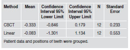

Fig.2: Graph of the results of the descriptive statistics shown in Table 1.
For comparative statistics, Analysis of Variance (ANOVA) was performed to compare the two techniques, the differences among the three patients studied and the position on the arch (upper and lower canines). No significant difference was found in any of the cases (Table 2).
Table 2: Main-effects ANOVA.

There is no significant difference at p = 0.05 between CBCT and LT, between upper and lower canines, or among patients.
DISCUSSION
The measurement of the height of the vestibular cortical bone in millimeters is lower in LT, possibly because the image resolution is lower and it is therefore not appreciable by this method when it is too thin. The twelve teeth studied by tomography, both methods (LT and CBCT) showed that during the period of orthodontic alignment of the teeth in these four patients, there was no significant loss of height in the vestibular cortical bone. Many studies have quantified the variations in bone height in patients undergoing orthodontic treatment with the use of mini-implants by performing the measurements on intraoral18, 19 or panoramic radiographs20, nevertheless, these techniques cannot be used to quantify the free surfaces because they provide twodimensional images, with the disadvantage of overlapping structures. The review of the literature found no report quantifying the vestibular cortical bone of canines to evaluate the effects of orthodontic treatments with mild forces, which is why we adapted this method. The advantage of using LT is that the magnification is uniform under low radiation doses of 1 to 30 μSv per slice21; however, the fact that images are blurred makes them difficult to interpret for a general practitioner. More recently, the interdental cortical bone as an anchor for miniimplants has been studied using CBCT22.
There are also studies that quantify bone increase and loss on free faces with heavy loads, in surgically assisted rapid palatal expansion, which showed differences in the height of cortical bones between pre- and post-treatment measurements23.
The method used in this study quantifies the length of the vestibular cortical bone directly, considering that measuring from the occlusal may mask tooth intrusions or extrusions, which could lead to an erroneous conclusion regarding bone gain or loss when in fact it is an effect of the treatment22. Other authors use the distance from the cortical bone of the crest to the amelocemental junction 24, 25 to measure bone loss, although intrusive and extrusive tooth movements are not identified by this method either. Although in our study the pre- and post-alignment measurements show no statistically significant difference in the comparison between methods, CBCT has uniform magnification with high contrast and resolution, and slices free from blurring, making it easier to identify the thin vestibular cortical bone layer, in addition to which it allows multi-plane reconstructions which provide another tool for studying bone tissue and its cortical plates.
CONCLUSION
LT is an efficient method for evaluating the cortical bone of the vestibular crest in canines when it is thick enough. When it is too thin, it is more difficult to see. The most adequate diagnostic technique will depend on the balance between radiological risk vs. diagnostic benefit, taking into account what needs to be seen in the image, which will depend on the clinical case and the treatment that the patient undergoes.
ACKNOWLEDGMENTS
This work was supported by grants from University of Buenos Aires, UBACYT Program O408 and 2010-2012 cod. 0020090200390. We thank Orthodontika Company for their collaboration with the F.O.U.B.A. Orthodontic Department.
1. Albertini J, Bechelli A. Oclusion y Diagnostico en Rehabilitacion Oral. Alonso. Buenos Aires: Medica Panamericana, 2004. [ Links ]
2. Tal H, Moses O. A comparison of panoramic radiography with computed tomography in the planning of implant surgery. Dentomaxillofac Radiol 1991;20:40-42. [ Links ]
3. Jacobs R, Mraiwa N, Van Steenberghe D, Gijbels F, Quirynen M. Appearance, location, course, and morphology of the mandibular incisive canal: an assessment on spiral CT scan. Dentomaxillofac Radiol 2002;31:322-327. [ Links ]
4. Liang X, Jacobs R, Lambrichts I. An assessment on spiral CT scan of the superior and inferior genial spinal foramina and canals. Surg Radiol Anat 2006;28:98-104. [ Links ]
5. Pohlenz P, Blessmann M, Blake F, Gbara A, Schmelzle R, Heiland M. Major mandibular surgical procedures as an indication for intraoperative imaging. J Oral Maxillofac Surg 2008;66:324-329. [ Links ]
6. Quirynen M, Lamoral Y, Dekeyser C, Peene P et al. CT scan standard reconstruction technique for reliable jawbone volume determination. Int J Oral Maxillofac Implants 1990; 5:384-389. [ Links ]
7. Peltola JS, Mattila M. Cross-sectional tomograms obtained with four panoramic radiographic units in the assessment of implant site measurements. Dentomaxillofac Radiol 2004; 33:295-300. [ Links ]
8. Monsour PA, Dudhia R. Implant radiography and radiology. Aust Dent J. 2008; 53 Suppl 1:S11-25. [ Links ]
9. Todd AD, Gher ME, Quintero G, Richardson AC. Interpretation of linear and computed tomograms in the assessment of implant recipient sites. J. Periodontol 1993;64:1243- 1249. [ Links ]
10. Scarfe WC, Farman AG, Sukovic P. Clinical applications of cone- beam computed tomography in dental practice. J Can Dent Assoc 2006; 72:75-80. [ Links ]
11. Ludlow JB, Davies-Ludlow LE, Brooks SL, Howerton WB. Dosimetry of 3 CBCT devices for oral and maxillofacial radiology: CB Mercuray, NewTom 3G and i-CAT. Dentomaxillofac Radiol 2006 Jul;35(4):219-226. Erratum in: Dentomaxillofac Radiol 2006;35:392. [ Links ]
12. Okano T, Harata Y, Sugihara Y, Sakaino R, Tsuchida R, Iwai K, Seki K, Araki K. Absorbed and effective doses from cone beam volumetric imaging for implant planning. Dentomaxillofac Radiol 2009;38:79-85. [ Links ]
13. Suomalainen A, Kiljunen T, Kaser Y, Peltola J, Kortesniemi M. Dosimetry and image quality of four dental cone beam computed tomography scanners compared with multislice computed tomography scanners. Dentomaxillofac Radiol 2009 Sep;38(6):367-78. [ Links ]
14. Miracle AC, Mukherji SK. Conebeam CT of the head and neck, part 2: clinical applications. AJNR Am J Neuroradiol 2009;30:1285-1292. [ Links ]
15. Ludlow JB, Ivanovic M. Comparative dosimetry of dental CBCT devices and 64-slice CT for oral and maxillofacial radiology. Oral Surg Oral Med Oral Pathol Oral Radiol Endod 2008;106:106-114. [ Links ]
16. Schulze D, Heiland M, Thurmann H, Adam G.. Radiation exposure during midfacial imaging using 4- and 16-slice computed tomography, cone beam computed tomography systems and conventional radiography. Dentomaxillofac Radiol 2004;33:83-86 [ Links ]
17. Tyndall DA, Brooks SL. Selection criteria for dental implant site imaging: a position paper of the American Academy of Oral and Maxillofacial Radiology. Oral Surg Oral Med Oral Pathol Oral Radiol Endod 2000; 89:630-637 CBCT. [ Links ]
18. Janson G, Bombonatti R, Brandao AG, Henriques JF, de Freitas MR. Comparative radiographic evaluation of the alveolar bone crest after orthodontic treatment. Am J Orthod Dentofacial Orthop 2003;124:157-164. [ Links ]
19. Bondemark L, Kurol J. Proximal alveolar bone level after orthodontic treatment with magnets, superelastic coils and straight-wire appliances. Angle Orthod 1997;67:7-14. [ Links ]
20. Schnelle MA, Beck FM, Jaynes RM, Huja SS. A radiographic evaluation of the availability of bone for placement of miniscrews. Angle Orthod 2004;74:832-837. [ Links ]
21. Frederiksen NL, Benson BW, Sokolowski TW. Effective dose and risk assessment from film tomography used for dental implant diagnostics. Dentomaxillofac Radiol 1994; 23:123-127. [ Links ]
22. Baumgaertel S, Hans MG. Buccal cortical bone thickness for mini-implant placement. Am J Orthod Dentofacial Orthop 2009;136:230-235. [ Links ]
23. Gauthier C, Voyer R, Paquette M, Rompre P, Papadakis A. Periodontal effects of surgically assisted rapid palatal expansion evaluated clinically and with cone-beam computerized tomography: 6-month preliminary results. Am J Orthod Dentofacial Orthop 2011;139:S117-128. [ Links ]
24. Lund H, Grondahl K, Grondahl HG. Cone beam computed tomography for assessment of root length and marginal bone level during orthodontic treatment. Angle Orthod 2010;80:466-473. [ Links ]
25. Lund H, Grondahl K, Grondahl H-G. Cone beam computed tomography evaluations of marginal alveolar bone before and after orthodontic treatment combined with premolar extractions. Eur J Oral Sci 2012;120:201-211. [ Links ]

