Servicios Personalizados
Revista
Articulo
Indicadores
-
 Citado por SciELO
Links relacionados
-
 Similares en
SciELO
Compartir
Latin American applied research
versión impresa ISSN 0327-0793
Lat. Am. appl. res. v.32 n.2 Bahía Blanca abr./jun. 2002
Effect of impeller clearance on power consumption of unsteadily forward-reverse rotating multiple impellers in an unbaffled agitation vessel
Masanori Yoshida,1* Akira Ito,1 Kazuaki Yamagiwa,1 Akira Ohkawa,1Masahiko Abe,2 Shuichi Tezura3 and Masuo Shimazaki3
1 Department of Chemistry and Chemical Engineering, Niigata University 8085, Ikarashi 2, Niigata 950-2181, Japan
2 Department of Industrial Chemistry. Science University of Tokyo, 2641 Yamazaki Noda, Chiba 278-8510, Japan
3 Shimazaki Mixing Equipment Co., Ltd, 24-2, Nishi Nippori 2-chome, Arakawa-ku Tokyo 116-0013, Japan
* Author to whom correspondence should be addressed. E-mail: myoshida@eng.niigata-u.acjp
Abstract — Power consumption of unsteadily forward-reverse rotating multiple impellers, a new cross type of impellers with four delta blades (CDs), was experimentally studied in an unbaffled agitation vessel containing water with a liquid heigh t-to-diameter ratio of 2. The effect of clearance on the power number of forward-reverse rotating double and triple CDs was compared with that of udidinationally rotating disk turbine impellers with six flat blades (Dls) in the baffled vesseL The result was discussed in relation to the difference in bulk flow pattern between the unbaffled vessel with CDs and the baffled vessel with Dls, The study also revealed that the value of power consumption for the forward-reverse rotating multiple CDs in the unbaffled vessel can be evaluated as the value for the single CD system multiplied by the number of impeller stages over a wide range of impeller clearances.
Keywords — Power Consumption; Unbaffled Agitation Vessel; Unsteadily Forward-Reverse Rotating Impellers; Multiple Impeller System; Impeller Clearance.
1. Introduction
Power consumption of impeller in agitation vessels is an important parameter not only required in selecting and designing the drive unit but also needed in characterizing the difference in transport phenomena within the vessel. For example, the volumetric mass transfer coefficient, a significant measure for scale-up of aerated agitation vessels, is closely related to the power consumption per unit volume or mass of liquid, i.e., the specific power input (Van't Riet, 1979), In other words, when an improvement in the volumetric coefficient is planned by varying operation conditions including the way of attachment of impellers in multi-stage configuration system, the magnitude of the intended volumetric coefficient is predicted through estimation of changes in the specific power input. In industrial agitation operations, deep vessels which have multiple impellers characterized by a liquid height-to-diameter ratio considerably larger than unity are frequently employed. For such a system, the importance is well known of the selection of impeller design and the determination of impeller arrangement, A number of studies have already been carried out on the relationship between the power consumption of steadily (=unidirectionally) rotating multiple impellers and their clearance in conventional vessels with baffles attached to avoid the formation of a purely rotational flow (Takeda et al., 1968b; Taguchi and Kimura, 1970; Nishikawa et al., 1976; Hudcova et al., 1989; Aimenante and Chang, 1998), These results can successfully be applied to design and operation of baffled vessels having steadily rotating multiple impellers.
On the other hand, there has recently been a growing interest in using the method that gives unsteady agitation action to fluid either by changing the direction or speed of impeller rotation, i.e., that allows the impeller to rotate unsteadily in liquid. In fact, some papers have been reported the operational characteristics of this kind of agitation vessel having unsteadily rotating impeller in relation to the specific power input (Lamberto et al., 1996; Ogawa et al., 1996; Nomura et al., 1997; Yao et al., 1998). As has been pointed out, improvement in performance (operational characteristics) of the agitation vessel is achievable under low power consumption by using unsteadily rotating impeller. However, these works dealt with the vessels having only unsteadily rotating single impeller and the results were not developed into the vessel having multiple impellers, which is likely to be more important from the viewpoint of industrial (=practical) application. In other words, this suggests that the previous works can hardly give knowledge on the power characteristics necessary as the basic data for design and operation of the vessel having unsteadily rotating multiple impellers, or more concretely, useful information on the effect of clearance on the power consumption of unsteadily rotating multiple impellers, etc.
Previously, as a novel type of aerated agitation vessel, we proposed an unbaffled vessel having unsteadily forward-reverse rotating multiple impellers, a cross type of impellers with four delta blades (CDs), whose rotation reverses its direction periodically (Yoshida et al., 1996), and this type of gas-liquid agitator was named "AJITER". A forward-reverse agitation in which a constant-angle impeller rotates changing its direction alternately provides sufficient dispersion of the fluid in the vessel without using baffles. The effect of clearance on the power consumption of unsteadily forward-reverse rotating multiple CDs must be elucidated so that we can design and operate AJITER as a novel type of agitation vessel with multiple impellers. In this work, we first investigated experimentally the effect of clearance on the power consumption of the forward-reverse rotating multiple CDs while comparing with that of the unidirectionally rotating impellers in a baffled vessel. We then tried to explain differences in the dependence of power number on the clearance between the unsteadily and steadily rotating impellers in terms of the difference in bulk flow pattern within the vessel. Furthermore, we discussed the advantage in designing when the present type of forward-reverse rotating CD is used in multistage configuration on the basis of the results obtained, in comparison with the vessel having unidirecUonally rotating disk turbine impeller (DT).
2. Method
A schematic diagram of the experimental set-up for forward-reverse rotation mode is shown in Fig. 1. The vessel of 250 mm inner diameter, Dt, was used. The depth of liquid, H, was held at Dt (250 mm) for single impeller configuration system and at twice Dt (500 mm) for multiple impeller configuration system, respectively. As the impeller, geometrically similar cross type of impellers, i.e., impellers with four delta blades (CDs), 120-240 mm in diameter (Di), were employed in single-, and two- and three-stage configurations for the vessel without baffles. A conventional impeller, a disk turbine impeller with six flat blades (DT), was adopted as the unidirectionally rotating impeller. Two different but geometrically similar sizes of DTs, 90 and 120 mm in Di were used under the fully baffled condition (four baffles, 0.1Dt in width, see Fig. 2), CDs, 120 and 160 mm in Di, were also employed in unidirectional mode of operation for comparison. The geometrical conditions such as Dt and H were the same as those for forward-reverse rotation mode. The distance from the bottom of the lowest impeller, Cb, was 75 mm. For multi-stage configuration system, the distance between the impellers on the shaft, Ci was varied from 0.1Di to 1.8Di. The average rotation rate of the forward-reverse rotating impeller and the rotation rate of the unidirectionally rotating impellers, Nr ranged from 75 to 400 rpm. All experiments for the two agitation modes were performed using deionized water at 298 K.

Figure 1. Experimental apparatus for forward-reverse rotation mode (Dimensions in mm).
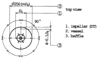
Figure 2. Arrangement of baffles when unidirectionally rotating impellers were used (Dimensions in mm).
The agitation power, Pm, was determined by measuring the torque with strain gauges fitted on the shaft. For the forward-reverse rotating impeller, the average values over one cyclic time of forward-reverse rotation of impeller were employed as Pm. The dimensionless numbers such as the power number, Np, and the Reynolds number, Rem, were calculated by the following equations, respectively:
 (1)
(1)
 (2)
(2)
These parameters of the forward-reverse rotating impeller system were based on the average impeller rotation rate.
3. Results and Discussion
3.1 Power Consumption of Single Impeller
Before investigating the power consumption of multiple impellers, the power consumption of single impeller was first examined in terms of power number. Figure 3 shows the relationship between the power number, Np1 and the impeller Reynolds number, Rem, for the forward-reverse rotating CD and the unidirectionally rotating impellers such as DT and CD. Np1 differed depending on impeller design and agitation mode, but was almost independent of Rem. Comparison of Np1 of the unidirectionally rotating impellers between the two impellers of different designs showed that the values of Np1 for the DT tended to be large compared with those for the CD. That is, the impeller with wider and larger number of blades exhibited higher Np1 values. This result seems to suggest that form drag plays a dominant role in the resistance of Liquid against the motion of both impellers (Shirakura and Obashi, 1984). For the difference between the two agitation modes, the value of Np1 for the forward-reverse rotating CD tended to be high compared with that for the unidirectionally rotating CD as can be seen from the figure. This may be attributed mainly to the phenomenon that the disturbed flow region behind the blades, a factor relating to the magnitude of the resistance of liquid against the motion of impeller, extends due to the unsteady motion of impeller (Okajima et al., 1997).
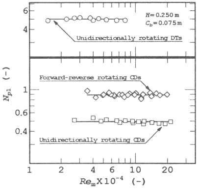
Figure 3. Relationship between Np1 and Rem.
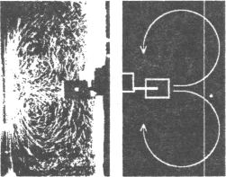
The differences in impeller design and agitation mode yield not only the difference in power number but also that in the bulk flow pattern within the vessel. Figure 4 shows the liquid flow patterns produced by the respective impellers. The flow pattern for the unidirectionally rotating CD was similar to that for the unidirectionally rotating DT, the well-known pattern having circulation loops with the characteristic radial discharge stream [Fig. 4 (a)]. When there is a difference in strength between the upper and lower loops, the discharge flow from the impeller deviates somewhat in the axial direction (Takeda el al., 1968a), As demonstrated in Fig. 4 (b), this phenomenon was observed also for the present type of CD. On the other hand, when the CD was allowed to rotate in forward-reverse mode, the tendency for the discharge flow to shift from the radial direction to the axial direction was more significant [Fig. 4 (c)].
(a) Unidirectionally rotating DT

(b) Unidirectionally rotating CD

(c) Forward-reverse rotating CD
Figure 4. Flow patterns produced by single impeller (a) baffled vessel with Di/Dt=0.48, (b) baffled vessel with Di/Dt=0.64, and (c) unbaflled vessel with Di/Dt=0.64, at Nr=3.33 s-1.
3.2 Power Consumption of Multiple Impellers
For most cases where the unidirectionally rotating impeller was used in the baffled vessel, roughly one to one and a half impeller per the Liquid depth equal to the vessel diameter is attached on the agitation shaft. On the basis of this fact, the power number was investigated when two and three impellers were used for the vessel with the liquid height-to-diameter ratio of 2. Figure 5 shows the relationship between the power number of dual impellers, Np2 and the clearance of impellers, Ci. In the figure, Np2 is divided by the power number of single impeller, Np1 and Ci is divided by the impeller diameter, Di. For the unidirectionally rotating DT, Np2 tended to decrease monotonically with decrease in Ci. This tendency is common to the result by Nishikawa et al. (1976) and that by Hudcova et al. (1989), For the unidirectionally rotating CD, Np2 first decreased slightly with decrease in Ci, then reached to a minimum at a certain value of Ci and tended afterward to reincrease. The difference in the dependence of Np2 on Ci between the impellers of different designs may be attributed mainly to that in impeller-impeller flow pattern interaction due to the different impeller design such as with or without disk (Nishikawa et al., 1976). The value of Np2 was found for the forward-reverse rotating CD to remain almost constant when Ci was varied. Figure 6 shows the relationship between the power number ratio of triple impellers, Np3/Np1, and the specific clearance of impellers, Ci/Di. Although the dependence of Np3 on Ci was similar to that of Np2 for the unidirectionally rotating impellers, the degree of its effect on Np3 was somewhat large compared with that on Np2. On the other hand, Np3 of the forward-reverse rotating CD exhibited an almost constant value independent of Ci.
Here, let's note the difference of the power number ratios, Np2/Np1 and Np3/Np1. The values of Np2/Np1 and Np3/Np1 for the unidirectionally rotating CD lie in the range close to 2 and 3, respectively, in contrast with those for the DT. The forward-reverse rotating CD gives the almost constant power number ratios, 2 and 3, in two- and three-stage configurations, respectively. When Np2/Np1 and Np3/Np1 are equal to 2 and 3, respectively, namely the power numbers for multiple impellers are equal to the number of impeller stages times the value for single impeller, each impeller is regarded to act independently without impeller-impeller flow pattern interaction (Takeda et al., 1968b; Taguchi and Kimura, 1970; Nishikawa et al., 1976; Hudcova et al., 1989; Armenante and Chang, 1998). As shown in Fig. 4, the liquid flow with the largest axial component was observed for the forward-reverse rotating CD among the impellers used. Figure 7 shows the liquid flow patterns produced by the respective multiple impellers. The differences in the flow patterns due to changes in the axial component in the discharge flows from impellers were observed. An increased axial component would result in a series of discharge flows between the adjacent impellers leading to a decreased impeller-impeller flow pattern interaction (Mochizuki et al., 1995), A less dependence of power number of the forward-reverse rotating multiple CDs on their clearance in the unbaffled vessel may be attributed mainly to the bulk flow with larger axial component.
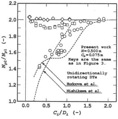
Figure 5. Relationship between power number ratio and specific impeller clearance for double-impeller system.
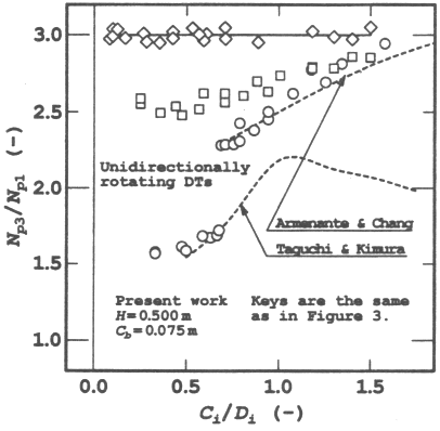
Figure 6. Relationship between power number ratio and specific impeller clearance for triple-impeller system.

Figure 7. Flow patterns produced by multiple impellers. (a) baffled vessel with Di/Dt=0.48 and Ci/Di=0.56, (b) baflled vessel with Di/Dt=0.64 and Ci/Di=0.42 and (c) unbaffled vessel with Di/Dt=0.64 and Ci/Di=0.42 at Nr=3.33 s-1
When the steadily rotating DT is used in multi-stage configuration in the baffled vessel, as seen from Figs 5 and 6, the values of the specific clearance of impellers, Ci/Di for which the values of the power number are equal to the number of impeller stages times the value for single DT, are in the range above about 1.5. In a Ci/Di range below 1.5, design of multiple DT system by developing single DT system becomes very complicated because the system must be treated as a single impeller that is a combination of impellers arranged (Mochizuki, 1992). In other words, this also means that in such a size of vessel as employed in this work, i.e., a deep vessel with the liquid height-to-diameter ratio of 2, which is frequently used in industrial agitation operations, the range of number of impellers that can be attached on the agitation shaft is restricted. On the other hand, when the unsteadily forward-reverse rotating CD is used in multi-stage configuration, the power number can be satisfactorily evaluated as the value for single CD multiplied by the number of impeller stages. That is, the power number for the forward-reverse rotating multiple CDs can be estimated from the simple proportional relation between the power number and the number of impeller stages. This would demonstrate that the multiple system using this type of unsteadily rotating CD can be designed without anxiety about the restriction in the impeller clearance range, i.e., the number of impeller stages, as encountered in the baffted vessel using the steadily rotating DT.
Moreover, in order to provide a more sound and generalized basis for design and operation of this type of agitation vessel, further studies will be necessary on the evaluation of the differences in the operational characteristics such as the mass transfer coefficient in systems treating different phases and the mixing time of liquids as viewed from changes in the power consumption when the clearance of impellers was varied, or the determination of the optimum geometrical arrangement of impellers based on their information, etc, in addition to an understanding of the effect of clearance on the power consumption of the unsteadily forward-reverse rotating multiple CDs presented in this work.
4. Conclusions
The power consumption of unsteadily forward-reverse rotating multiple impellers, i.e., a new cross type of impellers with four delta blades (CDs), was experimentally evaluated by varying the clearance of impellers and the number of impeller stages in the unbaffled agitation vessel containing water with the liquid height-to-diameter ratio of 2. In the baffled vessel using the disk turbine impellers with six flat blades (DTs) rotating steadily, the ratio of the power number of the multiple system to that of the single system changed depending on the clearance of impellers. In contrast, the power number of the forward-reverse rotating multiple CDs in the unbaffled vessel was almost independent of their clearance. These differences were attributed to those in the axial component in the bulk flow generated by the respective impellers. The result obtained in this work that the power number for the forward-reverse rotating multiple CDs can be satisfactorily estimated as the value for single CD multiplied by the number of impeller stage supports the easiness of engineering design when the present type of unsteadily rotating CD is used in multi-stage configuration.
Nomenclature
Cb = off-bottom clearance of the lowest impeller, m
Ci = clearance of impellers, m
Di = impeller diameter, m
Dt = vessel diameter, m
H = liquid depth in vessel, m
Np = impeller power number,-
Np1 = impeller power number in single impeller system, -
Np2 = impeller power number in dual impeller system, -
Np3 = impeller power number in triple impeller system, -
Nr = rotation rate of impeller, s-1
Pm = power consumption of impeller, W
Rem= impeller Reynolds number, -
Greek letters
μ = liquid viscosity, Pa s
ρ = liquid density, kg/m3
References
1. Armenante P. M. and G. M. Chang, "Power Consumption in Agitated Vessels Provided with Multiple-Disk Turbines", Ind. Eng. Chem. Res. 37, 284-291 (1998). [ Links ]
2. Hudcova V., V. Machon and A. W. Nienow, "Gas-Liquid Dispersion with Dual Rushton Turbine Impellers", Biotechnol. Bioeng. 34, 617-628 (1989). [ Links ]
3. Lamberto D. J., F. J. Muzzio and P. D. Swanson, "Using Time-Dependent RPM to Enhance Mixing in StiiTed Vessels", Chem. Eng. Sci. 51, 733-741 (1996). [ Links ]
4. Mochizuki M., SCEJ ed., Saikin no Kagaku Kogaku 44 Mixing, pp. 76-85, Kagakukogyosha, Tokyo (1992). [ Links ]
5. Mochizuki M., N. Takei, T. Satoh, K. Satoh and T. Akehata, "Power Required for Upper and Lower Impellers in Turbulent Mixing Vessels with Dual Impellers", Kagaku Kogaku Ronbunshu 21, 628-632 (1995). [ Links ]
6. Nishikawa M., K. Ashiwake, N, Hashimoto and S. Nagata, "Effect of Impeller Clearance on Power Consumption by Multi-Stage Impellers", Kagaku Kogaku Ronbunshu 2, 426-427 (1976). [ Links ]
7. Nomura T., T. Uchida and K. Takahasht, "Enhancement of Mixing by Unsteady Agitation of an Impeller in an Agitated Vessel", J. Chem. Eng. Japan 30, 875-879 (1997). [ Links ]
8. Ogawa K., C. Kuroda, H. Mizumori and S. Yoshikawa, "Effects of Unsteady Agitation by Reversing Revolution of an Impeller in an Agitated Vessel with Aeration", Kagaku Kogaku Ronbunshu 22, 91-97 (1996). [ Links ]
9. Okajima A., T. Matsumoto and S. Kimura, "Force Measurements and Flow Visualization of Circular and Square Cylinders in Oscillatory Flow", Trans. Japan Soc. Mech. Engrs B 63, 3548-3556 (1997). [ Links ]
10. Shirakura M. and R Ohashi, Fluid Mechanics (2), p. 155, Corona Publishing Co., Ltd., Tokyo (1984). [ Links ]
11. Taguchi H, and T. Kimura, "Studies on Geometric Parameters in Fermentor Design: Effects of Impeller Spacing on Power Consumption and Volumetric Oxygen Transfer Coefficient", J. Ferment. Technol. 48, 117-124 (1970). [ Links ]
12. Takeda K., T. Hoshino, K. Shimizu and T. Nishihata, "A Comparative Study of the Characteristics of Turbulent Mixing Vessels: Mixing Time, Power Consumption and Flow Patterns in Connection with (he Types and Construction of Details", Kagaku Kogaku 32, 369-375 (1968a). [ Links ]
13. Takeda K., T. Hoshino, H. Taguchi and T. Fujii, "Characteristics of the Multiple Impeller in Turbulent-Mixing Operation of a Deep Vessel", Kagaku Kogaku 32, 376-381 (1968b). [ Links ]
14. Van't Riet K., "Review of Measuring Methods and Results in Nonviscous Gas-Liquid Mass Transfer in Stirred Vessels", Ind. Eng. Chem. Process Des. Dev. 18, 357-364 (1979). [ Links ]
15. Yao W. G., H. Sato, K. Takahashi and K. Koyama, "Mixing Performance Experiments in Impeller Stirred Tanks Subjected to Unsteady Rotational Speeds", Chem. Eng. Sci. 53, 3031-3040 (1998). [ Links ]
16. Yoshida M,, A. Kitamura, K. Yamagiwa and A. Ohkawa, "Gas Hold-Up and Volumetric Oxygen Transfer Coefficient in an Aerated Agitated Vesset Without Baffles Having Forward-Reverse Rotating Impellers", Can. J. Chem. Eng. 74, 31-39 (1996). [ Links ]
Received: December 27, 2000 (by Editor in Chief).
August 10, 2001(by Subject Editor)
Accepted for publication: January 3, 2002.
Recommended by Subject Editor A. Cuitiño.


