Servicios Personalizados
Revista
Articulo
Indicadores
-
 Citado por SciELO
Links relacionados
-
 Similares en
SciELO
Compartir
Latin American applied research
versión impresa ISSN 0327-0793
Lat. Am. appl. res. v.34 n.4 Bahía Blanca oct./dic. 2004
Hydrodynamic analysis of the performance of stern flaps in a semi-displacement hull
M. Salas, J. Rosas and R. Luco
Institute of Naval and Maritime Sciences, Faculty of Engineering Sciences
University Austral of Chile. Casilla 567, Valdivia, Chile
msalas@uach.cl
Abstract ¾ The effects of stern flaps in the hydrodynamic performance of a semi-displacement hull were evaluated by systematic testing of scaled models in a towing tank. Chord length, span and flap angle were chosen as the main variable parameters to obtain six different stern flap configurations. The semi-displacement hull in conjunction with each stern flap was tested in order to assess the influence of each flap in resistance and running trim. The bare hull, i.e. without stern flap, was also tested to provide a suitable base for flap performance comparison. Main characteristics of the stern flaps were chosen according to existent recommendations provided in the relevant technical literature. The results showed good agreement with these recommendations; however, it was found that larger values of chord lengths and negative flap angles could possibly have a better performance on this craft.
Keywords ¾ Stern Flaps. Towing Tank. Hydrodynamics. Semi-displacement.
Nomenclature
| Lf | Flap chord length |
| a | Flap angle |
| LPP | Length between perpendiculars |
| BT | Transom beam |
| D | Ship Displacement |
| t | Trim, in degrees |
| Vs | Speed, in Knots |
| FN | Froude Number |
| FNÑ | Displacement Froude Number |
| CR | Residual Resistance Coefficient |
| l | Scale factor |
| hh | Hydrodynamic efficiency |
1. Introduction
A stern flap is an appendage built in form of a plate that extends aft of the transom in an angle relative to the buttock plane of the ship. Its interaction with the hull modifies the ship running trim, reduces propulsion resistance and increases maximum attainable speed. The critical parameters for a stern flap geometry design are: chord length (Lf), flap angle (a) referenced to an extension of the hull bottom and flap span across the transom. Figure 1 shows these parameters in a stern flap configuration. Secondary design aspects are: determination of platform shape, transverse thickness variations, and the detailed fairing into the hull, with special attention to the outboard edges. Generally, a simple radius corner is used to simplify design and construction.
The principal benefits that stern flaps produce are:
-Reduction in powering resistance. Experience has shown that this reduction is between 5 to 12%.
- Increase of maximum attainable speed.
-Beneficial propulsion interaction achieved.
- Modification of transom wave systems.
The reasons for the beneficial interaction due to the presence of a stern flap are different, depending if the flaps are fitted in a small craft or in a larger vessel. All stern flaps, independently of the size of the vessel, cause a force aft of the transom, modify the ship trim and the pressure distribution beneath the aft portion of the hull (Cusanelli et al., 1999). On small planning crafts, a stern flap affects the running trim angle by 4 to 5 degrees (Millward, 1976). This variation is the principal reason of the reduction in resistance on this type of hulls.

Figure 1: Characteristics of stern flaps.
In contrast to the planning hull case, a stern flap affects the trim angle by 0.1 to 0.3 degrees on displacements vessels. This amount of trim change does not produce significant reductions in resistance. The principal powering benefits on these vessels are attributable to the induced change in the flow field around the propeller. This flow field change reduces the drag on the stern zone and modifies the wave resistance of the ship.
2. Hydrodynamics of Stern Flaps
The hydrodynamic phenomena that are present on a vessel due to the presence of a stern flap is a subject under discussion. Thorough the combination of modern techniques of numerical flow computations and model experiments, this phenomena have been identified, and they should be viewed only as a general representation. The principal hydrodynamic mechanisms are discussed in the literature by Cusanelli (1996), Cusanelli and Karafiath (1997) and Cusanelli et al. (1999).
- Afterbody Flow Modifications: These cause the principal enhancement performance on a displacement hull. The stern flap reduces the flow velocity and increases the dynamic pressure under the hull. Model experiments have shown that this flow variation can affect an extension of 5 to 15% of LPP in the stern zone. Furthermore, the increment in the pressure field causes a greater lift force that produces a positive component in the movement direction of the ship.
The stern flap increases the exit flow velocity just under its trailing edge in comparison to the transom without flap. The increased velocity reduces the flow separation velocity and promotes a cleaner flow separation resulting in a reduction of the viscous pressure resistance.
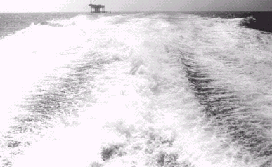
- Wave System Modifications: Localized flow around the stern zone without a stern flap is affected by lost of energy due to the presence of some mechanisms such as eddy-making, turbulence and generation of "white water", which may not propagate to the far field energy zone. At equivalent speeds, a stern flap affects the stern zone flow by reducing: height, slope, wave breaking and amount of "white water" in the trailing waves. Model experiments have shown a reduction of wave heights in the near-field stern wave and far-field wave energy systems. Figure 2 shows differences on the transom wave system with and without the presence of a stern flap on a patrol craft.
| |
Figure 2: Transom wave system with and without a stern flap. Courtesy: U.S. Navy.
- Lift and Drag Forces: A stern flap is a producer of lift and drag forces in all speeds and conditions. However, the beneficial interaction with the hull and propeller reduces the ship powering resistance. Drag and Lift forces grow larger with increasing chord length, span, angle (trailing edge down) and depth of immersion. Lift forces are greater than drag in all speed conditions.
- Secondary Hydrodynamic Effects: Other important mechanisms are: ship length increased, beneficial propulsion interaction, reduced ship sinkage and running trim modification. These last two mechanisms are key to maximize the performance on planning hulls.
2.1. Design Considerations
At-sea trials have shown that full scale stern flaps are effective in all speed range, with no negative effects at low speeds, however, the performance improvement is less significant at low speeds (Cusanelli and Forgach, 1995). The low speed performance penalty observed at model scale appears to be a phenomenon associated with stern flaps scaling effects, due to the differences between the flow conditions around model scale flap and those on the prototype. Due to these scaling effects it is generally the case that full-scale performance is better than the predicted one from scaled models.
At low speed stern flaps are totally submerged and wet. When the speed increases, the flow is transitional, periodically breaking free of the transom and flap and then coming back to wet it again. At high speed, the flow detaches cleanly and breaks-away from the trailing edge of the flap producing a significant reduction in resistance (Cusanelli, 1999).
Generally, a longer chord or an increase in flap angle produces a greater efficiency at high speeds. The design of a stern flap is a compromise of the operational and economical requirements of a vessel, and the selection of the critical parameters must be studied in all speed range. It is recommended to design stern flaps that reduce resistance over the speed/time/mission profile.
Several stern flap configurations have been tested for U.S. Navy military vessels at DTMB. They recommend to design flaps within the following ranges (Cusanelli and Karafiath, 2001):
- Chords between 0.5 to 2.5% LPP.
- Flap angles between 10 degrees trailing edge upward (negative angles) to 20 degrees trailing edge downward.
- Span must extend the maximum reasonable width across the transom, without affecting the wake of the corners and without requiring significant curvature around the bilge radius. In some cases, it has been found that a span approaching half of the transom width is optimal.
3. Stern Flap Hydrodynamic Analysis
3.1 General Description of the Vessel
In order to assess the hydrodynamic performance of existent flap design recommendations, six stern flap configurations were designed within the recommended ranges and model tested on a semi-displacement hull. The chosen vessel was the pilot craft "Aguja" of the Panama Canal Authority, a V-hull with twin shafts and 0.75 m. diameter fixed-pitch propellers. Hull sections of the craft are shown in Fig. 3. Main dimensions are given in Table I.
Figure 3: Sections of Tested Craft.
Table I: Main dimensions of tested vessel.

The craft has a bottom extension on the transom, this extension works as a stern flap, and its principal geometric characteristics are given in Table II.
Table II: Characteristics of existent stern flap

3.2. Description of Model and Experimental Procedure
A wood model, of scale factor l = 16, representing the pilot craft "Aguja", was constructed for this research project. No appendages were installed on the model, and all the experiments were done to the full load displacement, of 20.22 tons. Experiments were conducted for the conditions of hull without flap, with six different stern flaps designs, and with the existent bottom extension to measure the actual hydrodynamic performance of the vessel, in the range speed of 14 to 22 Knots, corresponding to FN of 0.6 to 0.95.
Tests were carried out in the towing tank of the Institute of Naval and Maritime Sciences at the University Austral of Chile. Tank dimensions are 45 m in length, 3 m width and 2 m water depth. Models are towed at the required speed (same full-scale FN ) by a cable connected to a dynamometer where drag is measured and directly recorded into a computer. Models are free to trim and trim angles were measured by video-recording the model, once the dynamic trim is achieved, against a graduated background.
Results from model experiments were extrapolated to the full scale craft applying the Froude Method and ITTC1 ship model correlation line, correlation allowance of ATTC2 of 0.0004 over the friction coefficient of the prototype and 0.0 over the friction coefficient of the model. All data presented in this investigation corresponds to the full scale craft, floating in smooth, deep salt water conditions, with a uniform standard temperature of 15o C.
To induce turbulent flow along the length of model hull, 12 turbulence stimulator studs (1/8'' diameter) were placed aft of the stem at approximately 10 percent of the waterline length, spaced 1.4 cms apart, according to the recommendations by Hughes. No particular turbulence transition location was aimed with this stud configuration.
3.3. Stern Flaps Selection
The tested stern flap configurations were designed following the existing recommendation about the ranges of effectiveness of the critical design parameters. Each flap design was tested in three angles: 0, 5 and 10 degrees. Main characteristics of the tested configurations are given in Table III and the geometry of tested stern flaps is shown in Fig. 4.
Table III: Characteristics of tested configurations.

________________________________________
1 ITTC: International Towing Tank Conference
2 ATTC: American Towing Tank Conference

Figure 4: Geometry of tested configurations.
Selection criteria for the optimum flap of the analyzed vessel are:
-Maximize reduction in ship resistance in the speed range of 20-22 Kn.
-Avoid any increase in ship resistance in the speed range of 14-20 Kn.
3.4. Stern Flaps Performance
A. Resistance
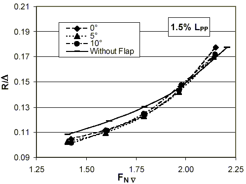
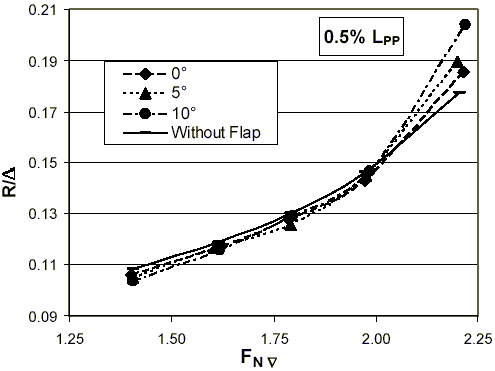
The curves of hydrodynamic resistance of the vessel obtained from model tests are shown in Figs. 5 and 6, with the results expressed in the non-dimensional form of resistance divided by displacement (R/D). In each figure, the resistance curve of the hull without flap was drawn to compare it with the hull plus flap conditions. It can be seen that the curves are basically similar and the presence of stern flaps reduced considerably the resistance in a wide range of speeds. All tested flaps had a good performance at low speeds.
Generally, for both spans, flap angles of 10 degrees were the most efficient for all tested chords at low speeds. At the same time as the speed increases, the performance of lower flap angles increases too, and at high speeds, flap angles of 0 degrees were the most efficient, except for the flap of chord length of 1.5% LPP, which had its best performance at an angle of 5 degrees (Fig. 5.)
Flaps of spans of 100% BT were the most efficient in all analyzed speeds. Generally, tested flaps began to loose efficiency at equivalent speeds of 1.82<FNÑ <2.15 (18-22Kn).
| a) b) c) |
Figure 5: Resistance/Displacement
Flaps of span 100% BT.
| a) b) c) |
Figure 6: Resistance/Displacement
Flaps of span 50% BT.
B. Residual Resistance Coefficient
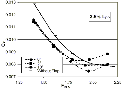
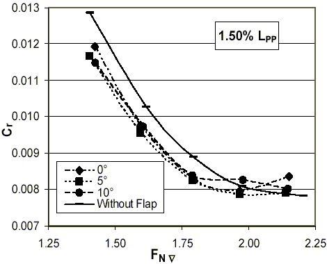
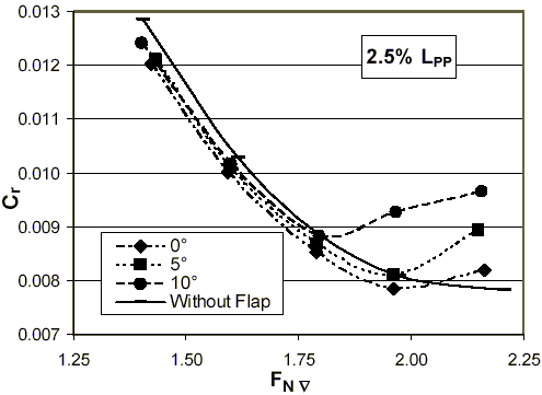
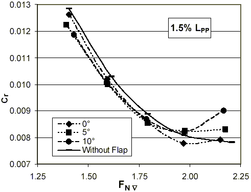
Residual resistance includes viscous and wave phenomena representing the highest loss of energy in this type of vessel. It is an important aspect in the study of the hydrodynamic performance of stern flaps. Figures 7 and 8 show residual resistance coefficients curves against speed for all tested flaps.
Generally, all curves have the same trend, higher flap angles reduce vessel's efficiency at high speeds. Flaps of span 100% BT produced higher reductions in resistance than spans 50% BT in all analyzed speeds. The greatest reduction was achieved by the flap of chord length of 2.5% LPP, span 100% BT and angle of 0o, at an equivalent speed of FNÑ = 1.95 (19.5 Kn), the reduction of resistance was approximately 9.75%. At high speeds, higher reductions are achieved by flaps with angle of 0o.The only exception was the flap of chord length of 1.5% LPP, span of 100% BT and angle of 10o (Fig. 7.b), which changes its trend at FNÑ ~2.0 increasing its performance, but producing a higher CR than the hull with no flap.
| a) b) c) |
Figure 7: Residual resistance coefficients
Flaps of span 100% BT.
For spans of 50% BT, the lowest values of CR were produced by flaps of angles 0o at equivalent speeds of 2.05<FNÑ <2.15 (20-21.5 Kn), and the highest reduction was in the order of 6.75%, at equivalent speed of FNÑ ~1.4. Flaps efficiency values are closely similar to CR reductions. Table IV presents the optimal flaps for both spans in all speed range.
| a) b) c) |
Figure 8: Residual resistance coefficients
Flaps of span 50% BT.
Table IV: Optimal flaps in all speed range.

C. Increment in Maximum Attainable Speed
The resistance reduction implies an increment in the maximum attainable speed of the vessel. The greatest increment was achieved by the flap of chord length 2.5% LPP, span 100% BT and angle 5o.
Tables V and VI show the increment of speed in all analyzed speeds for both studied flap spans. Due to stern flap scaling effects, it is expected that full scale stern flap performance will be even better than the corresponding one obtained in scaled models.
Table V: Increment of speed for flaps 100% BT

Table VI: Increment of speed for flaps 50% BT

The selection criteria of the optimum flap has been established previously. Considering these requirements, the flap of chord length 2.5% LPP, span 100% BT and angle of 0o was selected as the optimum flap of the tested configurations, with an improvement of 6.9% in hydrodynamic efficiency at 19 Kn.
D. Ship Running Trim
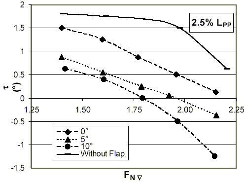
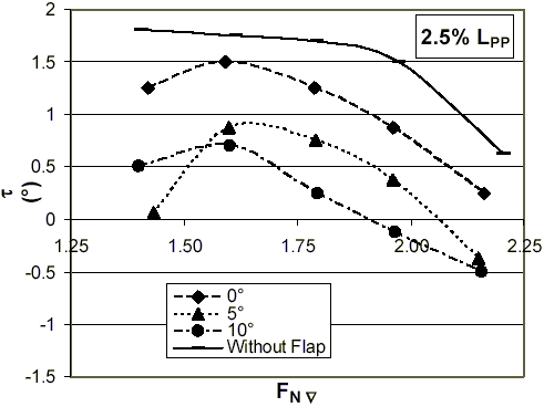
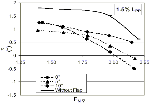
Figures 9 and 10 show trim angle curves of the tested flaps. All stern flaps reduced considerably the trim angles (bow down), except for the flap of chord length 0.5% LPP, span 50% BT and angle 0o.
Trim angles curves have the same trend for flaps with span 100% BT for the analyzed values of chord lengths and angles as shown in Fig. 9. These flaps produced higher differences in trim change than flaps of span 50% BT. The greatest change was produced by the flap of chord length of 2.5% LPP in angle of 10o, affecting in 1.9 degrees the original trim and giving a bow down trim of 1.25 degrees.
Different trends can be observed for flaps of span 50% BT as can be seen in Fig. 10. All flaps of chord lengths of 2.5% LPP increased the trim angle (bow up) at equivalent speeds of FNÑ <1.65, giving a bow down trim at higher speeds. The rest of tested flaps reduced the trim angle (bow down) in all speeds. The greatest change in trim was achieved by the flaps of chord lengths of 2.5% and 1.5% LPP at 10o, giving a bow down trim to 0.5o and affecting the original trim in 1.15o.
Comparing these results with resistance analysis, it can be seen that, it does not exist any similarity between the trend of trim changes and resistance reductions. This indicates that both parameters are independent in the hydrodynamic performance of this vessel. It is evident that variations on resistance are influenced by flow changes in the stern zone.
3.5. Actual Hydrodynamic Performance
There is an optimal flap angle for each vessel and operation condition, for example, Millward and Sparkes (1997) reported an optimum flap angle of 5o for a planning hull. In order to compare the performance of the optimum selected flap of the tested vessel (chord 2.5% LPP, span 100% BT and angle 0o), additional experiments were done for the condition of the hull with the existent bottom extension (chord 1.0% LPP, span 100% BT and angle 0o). The results were compared with the efficiency of the hull with no flap as is presented in Fig. 11 and Table VII. It can be seen that the existent bottom extension has a good performance in all the analyzed speed range, but its efficiency is lower than the optimum flap. However, the performance of these two conditions are similar at high speeds and both loose efficiency at approximately FNÑ ~2.1 (21 Kn). Figure 12 shows the trim changes for these conditions and the hull without flap.
| a) b) c) |
Figure 9: Trim changes - flaps of span 100% BT.
| a) b) c) |
Figure 10: Trim changes - flaps of span 50% BT.
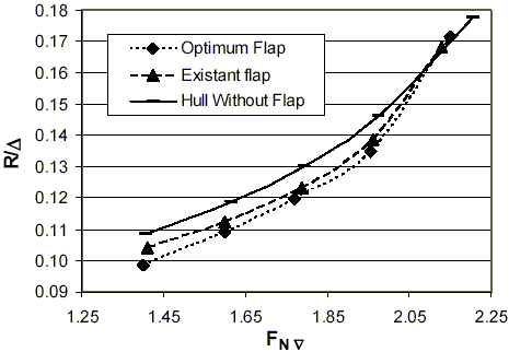
Figure 11: Resistance/Displacement

Figure 12: Trim changes
It was not possible to establish any relationship between trim changes and resistance reduction. This would indicate that drag reduction, for this type of vessel, is associated with modifications in the stern pressure field.
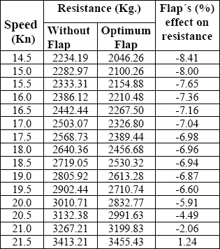
The measured model test data on the stern flap, expressed as a percentage of change in resistance due to the flap, is shown in Table VII. The data shows a substantial resistance reduction of approximately 7% over the speed range of 16.5 to 19.5 knots.
Table VII: Optimal flap effect on resistance
A preliminary estimate of achievable performance, for an optimized stern flap, can be made using the proprietary NSWCCD Resistance & Powering Department's (Code 5200) historical stern flap database. This regression-estimated performance represents what should be achievable, based on established trends in the database for all stern flaps as a whole. The performance is independent of the type of ship, so long as the designer has not strayed far from established prerequisites.
The results of the database preliminary assessment performed on the Aguja stern flap design, is plotted in Fig. 13. At the target speed of 18 knots, the database indicates a resistance reduction for the flap of approximately 7.15%. The model test reduction of 6.96%, is nearly equivalent to that of the preliminary estimate.
At low speeds, the author's flap design performs better than the database estimate, and at high speeds, the flap design performance was somewhat worse than the database estimate. These discrepancies might be due to different speed conditions, i.e. displacement or semi-displacement regimes.
3.6. Scaling Effects
A beneficial stern flap scaling effect has been identified at NSWCCD, through the testing of a model geosim series, CFD analysis, and correlation with full-scale trials on Navy destroyers.
A non-traditional ship/model scaling procedure, by which full-scale flap performance can be projected from model-scale data, is now utilized at NSWCCD. The stern flap scale effects, as represented in this analysis procedure, are dependant not only on the tested model scale ratio and speed range, but also on the magnitude of the model-scale performance increase.
Using the model-scale data supplied by the authors, an estimate was made with the NSWCCD flap scaling procedure, of the expected full-scale (projected) performance. The projected Aguja stern flap performance (with flap scaling effects), is presented on Fig. 13.
The beneficial stern flap scaling effect for the Aguja stern flap performance was 1.8%, consistent across speed, because the entire speed range tested was above the specified Fn 0.5 maximum of the Navy scaling study. Although this does not make a substantial difference in the projected stern flap data versus that of the model tests, it does indicate that even at the highest speed tested, 21.5 knots, the flap will provide beneficial resistance reduction.

Figure 13. Database and projected performance
(Courtesy D. Cusanelli, NSWCCD, USA)
4. Conclusions
Model tests were done to evaluate the hydrodynamic performance six stern flap configurations on a semi-displacement hull, in the speed range of 14 to 22 Kn. The tested vessel was the pilot craft "Aguja", property of the Panama Canal Authority. The principal geometric characteristics were designed following the existent recommendations, specially from DTMB, to compare its effectiveness in the project and design stages.
The results obtained from model tests show that:
- All tested flaps reduced resistance in a wide range of speeds.
- Generally, the lost of efficiency began at equivalent speeds of 1.82<FNÑ <2.15 (18-22Kn).
- Generally, higher values of flap angles are the most efficient at low speeds. At the same time as speed increases, lower flap angles show a better performance.
- Flap spans of 100% BT were the most efficient in all analyzed speed range. Considering the selection criteria, the flap of chord length 2.5% LPP, span 100% BT and angle 0o was selected as the optimum flap of the series, with an improvement in hydrodynamic efficiency performance of 6.9% at 19 Kn.
- There was not established any relation between trim changes and resistance reductions. It is suggested that benefits in the hydrodynamic performance are caused by flow changes in the stern zone. It is recommended to study these changes by CFD analysis.
- The efficiency of the tested configurations shows a good agreement with the existent recommendations. However, according to the trend of resistance curves from model experiments, possibly higher values of chord lengths and negative flap angles could produce better hydrodynamic performances.
In order to measure the actual hydrodynamic performance of the vessel, the hull was tested with the existent bottom extension. Results were compared with the conditions of hull with no flap and with the selected optimum flap. The results show that the extension has a good performance, but its efficiency is lower than the optimum flap. However, its performance tends to be similar at equivalent speeds of FNÑ ~2.1 (21 Kn).
Acknowledgments
The authors wish to express their gratitude to DID-University Austral of Chile; Dr. Adrian Millward (Univ. of Liverpool) and Mr. Oscar Amaris, from Panama Canal Authority, for granting access to information about pilot craft "Aguja".
Special gratitude is due to Mr. Dominic Cusanelli (NSWCCD Code 5200, USA) who carried out projected full scale flap performance calculations and database regression estimates. His support to the research presented in this paper is highly valued.
References
1. Cusanelli, D., "Stern Flap Powering Performance on the PC1 Class Patrol Coastal, Full Scale Trials and Model Experiments", Patrol '96 Conference, Dec. 1996, New Orleans, L.A. (1996). [ Links ]
2. Cusanelli, D., "U.S. Coast Guard Island Class 110 WPB: Stern Flap Evaluation and Selection (Model 5526)", Technical report NSWCCD-50-TR-1999/061, (1999). [ Links ]
3. Cusanelli, D. and Forgach, K., "Stern Flaps for Enhanced Powering Performance", Twenty-Fourth American Towing Tank Conference, Nov. 2-3, 1995, College Station, Texas. (1995). [ Links ]
4. Cusanelli, D. and Karafiath, G., "Integrated Wedge-Flap for Enhanced Powering Performance", Fourth International Conference on Fast Sea Transportation FAST 1997, July 21-23, 1997, Sidney, Australia. (1997). [ Links ]
5. Cusanelli, D. and Karafiath, G., "Stern Flaps", Professional Boatbuilder, April-May (2001). [ Links ]
6. Cusanelli, D., Karafiath, G., and Lin, Cheng Wen, "Stern Wedges and Stern Flaps for Improved Powering Performance - U.S. Navy Experience", SNAME Annual Meeting, Sept. 29 - Oct 2, 1999, Baltimore, M.D. (1999). [ Links ]
7. Millward, A., "Effect of Wedges on the Performance Characteristics of Two Planning Hulls", Journal of Ship Research, Vol. 20, No. 4, Dec. (1976). [ Links ]
8. Millward, A. and Sparkes, M., "An Investigation of the Performance of a Tri-hedral Planning Hull", IMarE Transactions, Vol. 109 Part 3, pp301-311, July (1997). [ Links ]


