


Servicios Personalizados
Revista

Articulo
 Inglés (pdf)
 Articulo en XML
 Referencias del artículo
 Enviar articulo por email
Indicadores
-
 Citado por SciELO
Links relacionados
-
 Similares en
SciELO
Similares en
SciELO
Compartir

 Permalink
Latin American applied research
versión impresa ISSN 0327-0793
Lat. Am. appl. res. v.38 n.3 Bahía Blanca jul. 2008
Lift and drag coefficients behaviour at low Reynolds number in an airfoil with Gurney flap submitted to a turbulent flow. Part 1
J. Colman, J. Marañón Di Leo, J. S. Delnero, M. Martínez, U. Boldes and F. Bacchi
Laboratorio de Capa Límite y Fluidodinámica Ambiental (LACLYFA), Facultad de Ingeniería, UNLP. Calle 116 e/47 y 48 - (1900) La Plata - Pcia. de Bs. As. - Argentina.
jcolman@ing.unlp.edu.ar, jmaranon@ing.unlp.edu.ar , delnero@ing.unlp.edu.ar , mmartinezk@ing.unlp.edu.ar , uboldes@ing.unlp.edu.ar , bacchi@ing.unlp.edu.ar
Abstract — Boundary layer wind tunnel experiments have been conducted in order to investigate the influence of a Gurney flap upon the aerodynamic behaviour of an HQ 17 airfoil. The airfoils, with and without the Gurney flap, were submitted to two different turbulent flows with the same mean wind velocity but with different turbulence structures. Lift and drag coefficients were calculated in both cases, then plotted and contrasted with low velocity laminar wind tunnel data of the HQ17 with and without miniflaps Gurney, obtained from Bechert et al. (2000) at the DLR, Technical University of Berlin, Germany. The results show that the Gurney flap acts enhancing the lift coefficient of the airfoil, and that its performance is almost independent of the scales of the incoming turbulence. The tests were performed at a turbulence intensity of 1.8% and 3.5% and at a Reynolds number of 3x10 5.
Keywords — Flow Control. Low Reynolds Number Airfoils. Turbulence. Aerodynamics.
I. INTRODUCTION
The performance of airfoils operating at low Reynolds numbers has been a topic of increasing attention during the last decades.
This interest was a consequence of a search for improving aircraft low speed performance as well as for improving the design of wind turbine blades (Fuglsang et al., 1999), rotors and propellers.
High-lift aerodynamics continues playing an important role in the design of a new aircraft. Improved high-lift performance can lead to increase range and payload, or decrease landing speed and field length requirements. Hence, there is a continuous need for improving the maximum lift and lift-to-drag ratio, L/D . Improved airfoil performance using a small trailing edge flap, was first reported by Liebeck (1980) from tests made on a Newman symmetric airfoil with a Gurney flap, in a non turbulent flow environment. Miniflaps, such as Gurney flaps, are small extensions at the trailing edge of an airfoil perpendicular to its lower surface. Its size is typically 0.5% to 2% of the airfoil chord length. These devices were first used by Dan Gurney, a race car driver, on a racing car wing, resulting in an increase of its maximum speed and its down force in cornering. Later, the Gurney flap was studied by Liebeck (1978). In his tests, Liebeck studied a Gurney flap of 1.25% the wing chord length, observing an increase of the lift and lift-to-drag ratio compared with the same airfoil without the flap. The Gurney flap acts as a mechanism of passive flow control. To explain the drag reduction at high angles of attack, Liebeck presented a model of the flowfield in the region of the Gurney flap, that model has been substantiated by flow visualization tests made in a water tunnel by Neuhart and Pendergraft (1988). The water tunnel tests showed that the presence of the Gurney flap provoked an extension in the region of attached flow on the upper surface of the wing, with a recirculation region behind the flap. This is consistent with a reduced form drag obtained at high lift coefficients using a Gurney flap. Later works confirmed this finding (Bloy and Durrant, 1995; Storms and Jang, 1994).
Selig et al. (1996) performed several experimental and computational analyses on low Reynolds number airfoils, in particular, on airfoils with Gurney flaps, disregarding the turbulence of the free stream.
The local velocities seen by a wing section are the result of the vectorial addition of the airplane velocity and the atmospheric velocities. Attitude changes produce lateral or vertical slip, and airplane rotations generating pitching, yawing and rolling moments.
The atmospheric surface layer, in which important flight operations take place, is characterised by complex turbulent flows. These flows are strongly influenced by the terrain roughness elements, like particular topography, suburban and urban areas, different plantations, etc.
The influence of turbulence on the resulting flow patterns around wing sections (airfoils) depends on the relation between airplane mean velocity to atmospheric turbulent velocities, among other factors. The turbulence induced by flow perturbations around an airfoil, influences the occurrence of attached flows, unsteady disordered separated flows and vortex generation. Representative wind tunnel experiments should reproduce the main turbulence characteristics of the regions in which a particular airplane is expected to operate. The turbulence intensity corresponding to turbulence I was 1.8% while the one corresponding to turbulence II was 3.5% (Hinze, 1985). In both cases the average speed was 10m/sec.
Over the years, the experimental study of turbulence structure effects on airfoil performance was scarce.
Green and Galbraith (1996) have been treating general aspects of the scenario, involving dynamic separation and reattachment on airfoils. Studies on an airfoil submitted to oscillating and translating motion in low Reynolds number flow were presented by Ohmi et al. (1990, 1991).
Turbulent gust, as well as fast pitching motions, can generate rapid angle of attack variations. With adequate caution, some oscillating airfoil experimental information may be applied to reveal aspects of the aerodynamics on non pitching wings, in a turbulent flow environment. Fluctuating angle of attack of the oncoming velocity, can promote the beginning of localised airfoil stall followed, in some cases, by the reattachment of the flow. Incipient dynamic stall phenomena have been studied by Gracey et al. (1996, 1997).
The usage of Gurney flaps, as a mechanism of passive flow control, could promote changes in the dynamic stall phenomena and lift enhancement, as well as an improved lift-to-drag ratio (L/D) upon an airfoil submitted either to a laminar or turbulent environment. The increment in the lift force is considered to be a consequence of the increased circulation provoked by the Gurney flap at the trailing edge.
The shape of the trailing edge is of paramount importance for the lift. In addition, it is worth mentioning (Henne, 1990) that the static pressure on the lower side upstream of the Gurney flap, is significantly higher than the value found at the end of the upper side of the airfoil. Consequently, traditional closure principles, such as the condition of the continuity of static pressure at the trailing edge, have to be abandoned here. Recent detailed investigations on the flow on diverging trailing edges have shed some light on the local flow structure (Pailhas et al., 1998). Enhanced performance of wind turbines, with Gurney flaps, has also been demonstrated (Kentfield, 1994). Bloy et al. (1997) studied, in a low velocity wind tunnel, the enhancement of airfoil performance using various types of Gurney flaps in a non turbulent environment.
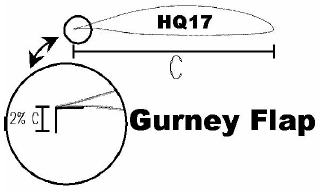
Figure 1. Gurney flap configuration
The purpose of this work is to contribute to a better understanding of the effect of the turbulence scales, upon the behaviour of the lift and drag coefficients of a HQ17 airfoil with a Gurney flap of 2% of the wing chord, submitted to a turbulent environment (Fig. 1).
In future works we will investigate the aerodynamics effects of different Gurney flaps over the HQ17 and others airfoils at low Reynolds numbers.
II. EXPERIMENTAL DETAILS
The experiments were carried out at the Boundary Layer and Environmental Fluid Dynamics Laboratory (LACLYFA) wind tunnel, at the Faculty of Engineering at the Universidad Nacional de La Plata, Argentina.
The closed section wind tunnel, equipped with an electronic speed control, which allows speeds up to 20m/sec, was described in Boldes et al. (1995). Its test section is 1.4m width and 1m height and its length to height ratio is 7.2. This tunnel is powered by a 50HP DC electric motor with an axial flow, variable velocity adjustable pitch blade propeller.
Special care was devoted in selecting turbulence generation procedures as close as possible to natural atmospheric mechanisms, according to modern boundary layer wind tunnel technique. At the entrance of the test section, background turbulence was generated by means of an array of vertical distributed, equally spaced horizontal airfoils, inducing different vertical deflections of the flow as shown in Delnero et al. (2005). Each airfoil could be individually rotated 360 degrees around its longitudinal axis.
Subsequently, the flow was processed by an arrangement of spires placed at the bottom, followed by a floor distribution of roughness elements of two different sizes, along the 7.2 meters long working section, also shown in Delnero et al. (2005).
The authors main goal was the achievement of two different turbulent oncoming flows, with the same mean velocity acting on the airfoils, but with turbulence structures of different scales (see Delnero et al., 2005). Thus, two types of turbulences were obtained: Turbulence I with predominance of large structures and Turbulence II with predominance of small structures. The turbulence time scales were determined by the first zero autocorrelation value criterion. For turbulence I, the time scale was 0.17sec, while for turbulence II it was 0.05sec. Using the frozen theory, a space scales of 1.7m and 0.5m was determined for turbulences I and II, respectively.
The reference mean velocity (U) was measured by means of a portable hot wire anemometer Dantec Flowmaster. This anemometer was placed 100cm upstream from the tested wing and 50cm above the wind tunnel floor. The tests were conducted at a reference mean velocity of 10m/sec, corresponding to a Reynolds number based on the reference mean velocity and the wing chord of 3 x 10 5.
The tested model was an untwisted wing with a rectangular platform of 45cm. of chord length and 80cm of span. The models were horizontally placed in the test section as shown in Fig. 2 (in order to see some details, the end plates were removed from the wing model in the Fig. 2).
To ensure that the airfoil would be submitted to a bidimentional flow, two big end plates, similar that used by Bechert et al. (2000), were located at the end of wing tips (Fig. 3). Smoke and wind threads were used to verify the flow bidimensionality.
For each flow configuration the model was tested within the range of -10 degrees and 20 degrees of angle of attack.
The present experiments examine the lift and drag behavior of the HQ17 airfoil, which was designed by Horstmann and Quast from DLR-Brunswick (Germany), to be applied on high performance sailplanes. The authors selected this airfoil for their first experiments with Gurney flaps at low Reynolds numbers, due to the possibility to contrast the obtained data with the extensive experimental data from Bechert et al. (2000) obtained at the DLR. Those authors performed their experiments in a laminar low velocity wind tunnel at a range of Reynolds numbers from 5 x 10 5 to 1 x 10 6.
A lack of computational and/or experimental data was observed about the aerodynamic behavior of airfoils at Reynolds numbers below 5 x 10 5 with Gurney flaps in turbulent environments. For that reason, we chose to perform our experiments at such low Reynolds numbers.
The experiments were repeated for the two types of turbulent flows and for the two airfoil configuration (with and without the Gurney flap). Turbulent velocities were acquired by means of a six channel Dantec Streamline constant temperature anemometer. The two components aerodynamic balance, built by the authors according to Tusche (1984), is based on strain-gages

Figure 2. Experimental setup view.
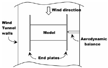
Figure 3. Plant view layout.
type cells, arranged as a double Wheastone bridge. This device acquires data from horizontal and vertical loads, simultaneously.
The incoming data is processed by Vishay series 2310 signal conditioners and amplifiers.
The section lift and drag coefficients (Cl and Cd) were measured for the two turbulent flow configurations, and for the two wing configurations (with and without the Gurney flap). Then, Cl vs. Cd and Cl vs. angle of attach (α) were plotted to be compared with the same plots of the data obtained by Bechert et al. (2000) in a non turbulent environment. Temperature was continuously measured in order to adjust the air density.
Interesting computational experiments with Gurney flaps applied to the HQ17 airfoil were also performed by Schatz et al. (2004).
Our experiments were developed in three steps:
- Generation of two velocity profiles with the same mean velocity distribution but with different turbulence configurations (I and II).
- Construction of the model and set up into the wind tunnel.
- Performance of the experiments, processing of the experimental data, and evaluation of the influence of the turbulence scales on the wing performance.
Turbulence intensity distributions are plotted in Fig. 4. The autocorrelation functions for both types of turbulence are plotted in Fig. 5. In such figure the different scales of the two types of turbulence can be appreciated.
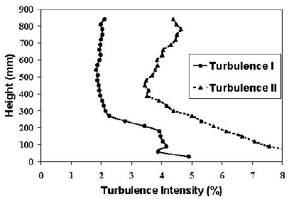
Figure 4. Turbulence Intensity Distributions

Figure 5. Autocorrelation Coefficients for turbulence I and II.
Aspects of the turbulence scale of the embedded flow structures can be appreciated in the wavelet analysis of the horizontal velocity component shown in Fig. 6 and 7 (Delnero et al., 2005).
Figure 8 shows the power spectra distributions of both signals obtained from the wavelet analysis (Figs. 6 and 7).

Figure 6. Wavelet Transformation Coefficients Map for Turbulence I (longitudinal component)

Figure 7. Wavelet Transformation Coefficients Map for Turbulence II (longitudinal component)
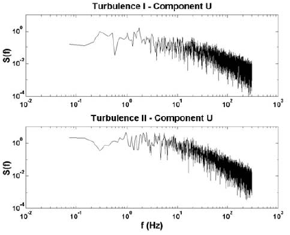
Figure 8. Power Spectra Distribution
III. ANALYSIS OF THE RESULTS
The blockage correction for wind tunnel effects was applied (Pope et al., 1999). The measured Cl versus α evolution of the HQ17 without the Gurney flap for the two turbulent configurations and for the laminar case are displayed in Fig. 9. This figure, also, shows the curves for the 2% Gurney flap. Figure 10 shows the lift to drag behavior for the case of the model with and without the Gurney flap, respectively.
Our experiments showed, for the plain wing and for the wing with Gurney flap, submitted to both turbulent configurations, lower Cl vs. α slopes than those obtained by Bechert et al. (2000). Also there was no indication of the existence of laminar separation bubbles on the upper surface, for angles of attack below stall.
Comparing the plain wing performance for laminar and turbulent flows, the same maximum lift coefficient could be observed. Nevertheless, the increment of the stall angle of attack for both turbulent flow configurations was significant, in comparison to the data obtained by Bechert et al. (2000).
This known behavior is due to the ability of turbulent boundary layers to overcome larger adverse pressure gradients retarding flow separation.
In both cases -laminar and turbulent- the Gurney flap acts increasing the section lift coefficient and the Cl vs. α slope (Fig. 9)

Figure 9. Cl versus α evolution for different configurations.

Figure 10. Cl versus Cd evolution for different configurations.
The lift gain obtained with Gurney flap is, unfortunately, coupled to an increase in drag. The extra drag produced by the presence of the Gurney flap is, partially, due to the flow instability that it produces. Figure 11 shows, according to Jang et al. (1998), the probable flow pattern in the near trailing edge region of the wing with Gurney flap. Such authors suggest that the vortices in the wake are shed alternately in the similar fashion to the von Karman vortex street behind a cylinder. Also Schatz et al. (2004) described similar characteristics of the Gurney flap wake, for Reynolds number close to 1.000.000. The present authors found similar wake pattern for Reynolds number of 440.000. Some of the particular wake structure will be described by the authors in a future Part 2 of the present work.
We could conclude that the Gurney flap, in a turbulent environment, acts enhancing the section lift coefficient, and increasing the drag for both types of turbulence. Moreover, the performance of the airfoil is almost independent of the turbulence scales (types I and II). However, in all cases, the performance in a laminar environment is better than in a turbulent one.
An unexpected result was found when regarding the Gurney flap behavior in turbulence. Turbulent flow could act, apparently, in such a way that makes the airfoil be almost independent from the turbulent scales. We can see in Fig. 9 that, for the plain wing, the lift coefficient in turbulence I presents higher values than in turbulence II, for the same angles of attack. However, that difference could not be appreciated on the airfoil with Gurney Flap.
The obtained results suggest that further experiments should be performed, in order to explore the effects of different miniflap sizes upon the aerodynamic coefficients in a turbulent environment.

Figure 11. Hypothesised trailing edge flow structure behind a Gurney flap (after Jang et al., 1998; Chung, 2004; and Schatz et al., 2004).
ACKNOWLEDGEMENTS
The authors are gratefully for the support of the Aeronautical Department, the Boundary Layer and Environmental Fluid Dynamics Laboratory and the useful collaboration of the aeronautical engineer Gerónimo Marinangelli in processing part of the experimental data. Julio Marañón Di Leo is Scientific Researcher of CONICET.
REFERENCES
1. Bechert, D.W., R. Meyer and W. Hage, "Drag reduction of airfoils with miniflaps. Can we learn from dragonflies?" AIAA Paper 2000-2315 (2000). [ Links ]
2. Bloy, A.W. and M.T. Durrant, "Aerodynamic Characteristics of an aerofoil with Small Trailing Edge Flaps", Wind Engineering, 19, 167-172 (1995). [ Links ]
3. Bloy, A.W., N. Tsioumanis and N.T. Mellor, "Enhanced Aerofoil Performance Using Small Trailing-Edge Flaps", Journal of Aircraft, 34, 569-571, (1997). [ Links ]
4. Boldes, U., J. Colman and V. Nadal Mora, "The Boundary Layer Wind Tunnel at the Faculty of Engineering, University of La Plata, Argentina". Latin American Applied Research, 25, 75-85 (1995). [ Links ]
5. Delnero, J.S., J. Marañón Di Leo, F.A. Bacchi, J. Colman and U. Boldes, "Experimental determination of the influence of turbulence scale on the lift and drag coefficients of low Reynolds number airfoils". Latin American Applied Research, 35, 183-188 (2005). [ Links ]
6. Fuglsang, P., K.S. Dahl and I. Antoniou, "Wind Tunnel Test of the Riso A1-18, Riso A1-21 and Riso A1-24 Airfoils", Riso-1112 (EN), Final Draft (EFP 98 Project experimental verification of the Riso-A airfoil family, Riso National Laboratory (1999). [ Links ]
7. Gracey, M.W., A.J. Niven, F.N. Coton, R.A. Galbraith and D. Jiang. "A correlation indicating incipient dynamic stall", Aeronautical Journal, 100, 305-311 (1996). [ Links ]
8. Gracey, M.W., F.N. Coton and R.A. Galbraith, "On the prediction of unsteady stall criticality", Aeronautical Journal, 101, 525-532 (1997). [ Links ]
9. Green, R.B. and R.A. Galbraith, "Comment on dynamic airfoil flow separation and reattachment", Journal of Aircraft, 33, 1211-1216 (1996). [ Links ]
10. Henne, P.A., "Innovation with computational aerodynamics: The divergent trailing edge airfoil", Progress in Aeronautics and Astronautics, V-125, AIAA (1990). [ Links ]
11. Hinze, J.O., Turbulence. Ed. Mc Graw-Hill (1975). [ Links ]
12. Jang, C.S., J.C. Ross and R.M. Cummings, "Numerical investigation of an airfoil with a Gurney flap", Aircraft Design, 1, 75-88 (1998). [ Links ]
13. Kentfield, J.A.C., "Theoretically and experimentally obtained performances of Gurney flap equipped wind turbines", Wind Engineering, 18, 63-74 (1994). [ Links ]
14. Liebeck, R.H., "Design of subsonic airfoils for high lift", Journal of Aircraft, 15, 547-561 (1978). [ Links ]
15. Liebeck, R.H., "Design of Airfoils for High Lift", AIAA, 80-3034 (1980). [ Links ]
16. Neuhart, D.H. and O.C. Pendergraft, "A water tunnel study of Gurney flaps". NASA Technical Memorandum, 4071 (1988). [ Links ]
17. Ohmi, K.H., M. Coutanceau, Ta Phouc Loe and A. Dulieu, "Vortex formation around an oscillating and translating airfoil at large incidences", J. Fluid Mech., 211, 37-60 (1990). [ Links ]
18. Ohmi, K.H., M. Coutanceau, O. Daube and Ta Phouc Loe, "Further experiments on vortex formation around an oscillating and translating airfoil at large incidences", J. Fluid Mech., 225, 607-630 (1991). [ Links ]
19. Pailhas, G., P. Sauvage, I. Touvet and E. Coustols, "Flow field in the vecinity of of a thick cambered trailing edge", 9th International Symposium on Applications of Laser Techniques to Fluid Mechanics, 13-16 July, Lisboa, Portugal, III.3 (1998). [ Links ]
20. Pope, A., J. Barlow and W. Rae, Low-speed wind tunnel testing, John Wiley & Sons, New York (1999). [ Links ]
21. Schatz, M., B. Gunther and F. Thiele, "Computational Modeling of the Unsteady Wake behind Gurney-Flaps", AIAA, 2417 (2004). [ Links ]
22. Selig, M., C. Lyon, P.G.C. Ninham, A. Broeren and A. Gopalarathnam, Summary of Low Speed Airfoil Data, University of Illinois, USA, 2 (1996). [ Links ]
23. Storms, B.L. and C.S. Jang, "Lift Enhancement of an Airfoil Using a Gurney Flap and Vortex Generators", Journal of Aircraft, 31, 542-547 (1994). [ Links ]
24. Tusche, S., "Interner Bericht: Beschreibung des Konstruktiven Aufbaus und Kalibrierung von 6-Komponenten-DMS Windkanalwaagen", DFVLR Interner Bericht 29112-83 A 11 (1984). [ Links ]
Received: October 19, 2005.
Accepted: July 25, 2006.
(In final form: September 5, 2007.)
Recommended by Subject Editor Walter Ambrosini.

