Servicios Personalizados
Revista
Articulo
Indicadores
-
 Citado por SciELO
Links relacionados
-
 Similares en
SciELO
Compartir
Latin American applied research
versión impresa ISSN 0327-0793
Lat. Am. appl. res. v.34 n.1 Bahía Blanca ene./mar. 2004
Mixing characteristics of liquid phase in an unbaffled vessel agitated by unsteadily forward-reverse rotating multiple impellers
Masanori Yoshida1,*, Yoji Taguchi1, Kazuaki Yamagiwa1, Akira Ohkawa1, Masahiko Abe2, Shuichi Tezura3 and Masuo Shimazaki3
1 Department of Chemistry and Chemical Engineering, Niigata University, 8050, Ikarashi 2, Niigata 950-2181, Japan
2 Department of Industrial Chemistry, Science University of Tokyo, 2641, Yamazaki, Noda, Chiba 278-8510, Japan
3 Shimazaki Mixing Equipment Co., Ltd., 24-2, Nishi Nippori 2-chome, Arakawa-ku, Tokyo 116-0013, Japan
* myoshida@eng.niigata-u.ac.jp
Abstract — Mixing characteristics of liquid phase in an unbaffled vessel containing water with a liquid height-to-diameter ratio of 2 agitated by unsteadily forward-reverse rotating multiple impellers, a cross type of impellers with four delta blades (CDs), were experimentally studied in comparison with that in a baffled vessel agitated by steadily unidirectionally rotating disk turbine impellers with six flat blades (DTs). For the forward-reverse as well as unidirectional modes of operation, the mixing time in multiple impeller system was larger than that in single impeller system with a liquid height-to-diameter ratio of 1. The ratio of mixing time in multiple impeller system to that in single impeller system was small for the forward-reverse agitation mode compared with that for the unidirectional agitation mode. The result was discussed in relation to the difference in bulk flow pattern between the unbaffled vessel with forward-reverse rotating CDs and the baffled vessel with unidirectionally rotating DTs.
Keywords — Mixing Time. Unbaffled Agitation Vessel. Unsteadily Forward-Reverse Rotating Impeller. Multiple Impeller System. Bulk Flow Pattern.
I. INTRODUCTION
In industrial agitation operations, deep vessels with multiple impellers characterized by a liquid height-to-diameter ratio larger than unity are frequently employed for practical purposes to get high volumetric mixing and to reduce the floor area occupied by the equipment in the factory. For such a system, it is well known the importance of the impeller design and the determination of impeller arrangement (Nishikawa et al., 1976; Hudcova et al., 1989; Armenante and Chang, 1998; Armenante et al., 1999). For conventional baffled vessels having steadily unidirectionally rotating multiple impellers, the impellers have been arranged on the shaft with the clearance and number determined on the basis of the data on their power consumption. However, whether or not design of the multiple impeller vessel is reasonable in view of operational characteristics is uncertain.
A primary way to investigate the feasibility of design for the multiple impeller vessel is to evaluate the mixing time of liquid phase which is a fundamental parameter needed not only for homogenization operation of liquid phase but also for mass transfer operation treating dispersions such as gas-liquid mixtures and solid-liquid mixtures. It seems that the results of few studies on the mixing time in baffled vessels having unidirectionally rotating multiple impellers (Komori and Murakami, 1988; Cronin et al., 1994; Jahoda and Machon, 1994; Vasconcelos et al., 1995) have been used as data for design and operation.
Previously, we proposed an unbaffled vessel having unsteadily forward-reverse rotating multiple impellers, a cross type of impellers with four delta blades (CDs), whose rotation reverses its direction periodically, and this type of agitator was named "AJITER" (Yoshida et al., 1996). For CDs in AJITER, the effect of clearance on the power consumption of impellers was elucidated, which is basic for design of the multiple impeller vessel (Yoshida et al., 2002). In order to provide a more sound and generalized basis for design and operation of AJITER, in addition to clarification of the power characteristics of impellers, further study on the mixing characteristics of liquid phase in a vessel is necessary. In this work, the way of arrangement of CDs in multiple fashion was first established, based on the dependence of power consumption on the clearance of forward-reverse rotating multiple CDs in an unbaffled vessel. For the vessel constructed, the effect of the number of impellers on the mixing time was then evaluated experimentally in comparison to that for a baffled vessel having unidirectionally rotating disk turbine impellers (DTs).
II. METHODS
As the forward-reverse rotating impeller, a cross type impellers with four delta blades (CDs), 120-240 mm in diameter (Di), were employed for an unbaffled vessel. A conventional impeller consisting of a disk turbine impeller with six flat blades (DT), was adopted as the unidirectionally rotating impeller. DTs, 90-150 mm in Di, were used under the fully baffled condition (four baffles, 0.1-fold inner diameter of vessel in width). A schematic diagram of the experimental set-up is shown in Fig. 1. The vessel of 250 mm inner diameter, Dt, was used. The depth of liquid, H, was held at twice Dt (500 mm). The geometrical conditions such as Dt and H were common to the forward-reverse and unidirectional modes of operation, except for the use of the unbaffled or baffled vessel. The distance from the bottom of the lowest impeller, Cb, was 75 mm. The distance between the impellers on the shaft, Ci, varied in multiple impeller configuration, ranging from 0.1Di to 1.8Di. The average rotation rate of the forward-reverse rotating impeller and the rotation rate of the unidirectionally rotating impeller, Nr, ranged from 50 to 350 rpm. Control experiments in single impeller configurations for the respective agitation modes were performed under the condition of H=Dt (250 mm) and Cb=75 mm. For all experiments, deionized water was used at 298 K.

Fig. 1: Schematic flow diagram of experimental apparatus. Dimensions in mm.
The power consumption of the impellers, Pm, was determined by measuring the torque with the strain gauges fitted on the shaft. While the power consumption of the impellers in the unidirectional agitation mode is independent of time, that in the forward-reverse agitation mode is unsteady due to periodical change in the impeller rotation rate and that in the shaft torque. In the latter mode of operation, the time-weighted average values over one cyclic time of forward-reverse rotation were employed as Pm. The power number, Np, of unidirectionally rotating impellers is defined by the following equation:
Np=Pm/ρNr3Di5 (1)
For the forward-reverse rotating impellers, Np was calculated using the average values as the time-dependent variables on the right side of Eqn (1), Pm and Nr, respectively.
Batch mixing time of liquid phase was determined using a tracer technique (Kramers et al., 1953; Kamiwano et al., 1967). The concentration fluctuation of 0.001-fold liquid volume of passive tracer (1 mol/L, KCl aqueous solution) was examined as a function of time from its rapid release into liquid agitated at the measured Nr. The concentration fluctuation was evaluated by measuring the difference in electrical conductivity of liquid between the two positions with the platinum wire-made electrode cells (Fig. 1) placed opposite one another near the vessel wall. The two electrode cells were put in a bridge using the electricity supplied as alternating current. The tracer liquid was fed from above the free surface at a position near the upper cell by a small magnetic valve connected with a limit switch. The arrangement of the electrode cells and magnetic valve in the multiple impeller vessel were shown in Fig. 1. For single impeller systems (H=250 mm), the distance between the upper cell and liquid surface, and the distance between the lower cell and vessel bottom were the same as those for multiple impeller systems (H=500 mm). A block diagram of the concentration measuring system is shown in Fig. 2. At the same time as the tracer liquid was released, the data processing system operated by the limit switch recorded the output voltage from the bridge circuit corresponding to the difference in electrical conductivity, i.e., concentration of KCl (Fig. 3). The mixing time, Tm, was defined as the time from the release of the tracer liquid until the fluctuation was within 5 % of the maximum value of voltage (Shiue and Wong, 1984; Yahata et al., 1985). Moreover, although there was a density difference of about 7 % between liquid within the vessel and tracer liquid, it was ascertained beforehand that mixing due to natural convection could be neglected under the experimental conditions used.
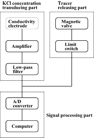
Fig. 2: Block diagram of KCI concentration measuring system.
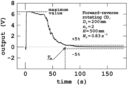
Fig. 3: Time-course of output.
III. RESULTS AND DISCUSSION
A. Arrangement of Impellers in Multiple Impeller System
Based on the power characteristics of the multiple impellers such as forward-reverse rotating CDs and unidirectionally rotating DTs, shown in previous work (Yoshida et al., 2002), the way of arrangement of the impellers in multiple fashion was first established. The distance from the bottom of the lowest impeller, Cb, was fixed at 75 mm. The impellers were set equidistantly on the shaft in its section (425 mm in distance) between the lowest impeller and liquid surface (see Fig. 4).

Fig. 4: Arrangement of impellers in multi-stage fashion. Dimensions in mm.
So, there is the following relation between the number of impellers, ni, and the clearance of impellers, Ci:
ni = 425/Ci (2)
The power consumption of multiple impellers changes depending on their clearance. This effect can be described in terms of the differences in the ratio of power number for multiple impellers, Npn, compared to that for single impeller, Np1, varying the impeller clearance. When Npn/Np1=ni, the impellers on the shaft are regarded to act independently of each other without impeller-impeller flow pattern interaction (Hudcova et al., 1989). Arrangement of the impellers with such clearance has the advantage of design due to ability to estimate simply the power consumption and a higher efficiency of energy transmission to fluid (Mochizuki, 1992). The condition on the impeller clearance where Npn/Np1= ni was found out on the basis of the data in dual impeller system that is most fundamental among multiple impeller systems. The range of the number of impellers satisfying such condition was then determined. Figure 5 shows the relationship between the power number ratio for dual impellers, Np2/Np1, and the impeller clearance, Ci.

Fig. 5: Relationship between Np2 and Ci
In the figure, Ci is divided by the impeller diameter, Di. According to the results shown in the figure, when unidirectionally rotating DTs are used in the baffled vessel, the system with values of the specific impeller clearance, Ci/Di, ranged above about 1.5 satisfies the condition where the power number ratio, Np2/Np1, is equal to 2. For respective Dis, based on the ranges of Ci, the ranges of ni were determined from Eqn (2). These are listed in Table 1.
Table 1. Determination of the number of impeller stages based on the power consumption.
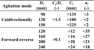
In the experiment, for reference, DTs were used in the range of ni up to four. For forward-reverse rotating CDs in the unbaffled vessel, the experimental result that Np2/Np1 is equal to 2 in the range of Ci/Di above 0.1 suggests use of about 20 impellers. In this work, taking practical design into consideration, CDs were used in the range of ni from two to eight.
For the number of impellers shown in Table 1, their power consumptions were evaluated in terms of the power number. For any mode of operation, the power number remained almost constant when the impeller rotation rate was varied. This suggests that the flow generated by forward-reverse rotating CDs and that generated by unidirectionally rotating DTs are in turbulent regime. Figure 6 shows the relationship between the power number ratio for multiple impellers, Npn/Np1, and the number of impellers, ni. The solid line in the figure represents that Npn/Np1=ni. The values of Npn/Np1 for forward-reverse rotating CDs agreed with ni within approximately 10 %. In the unidirectional agitation mode, Npn/Np1 for triple DTs and that for fourfold DTs exhibited the values smaller than the corresponding nis, 3 and 4, respectively, reflecting decrease of the power number with decrease of the impeller clearance as shown in Fig. 5. These support the above predictive results of the power consumption of multiple impellers on the basis of the data in dual impeller system.
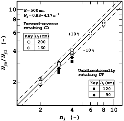
Fig. 6: Relationship between Npn and Ni.
B. Mixing Time
The mixing characteristics of liquid phase were then examined for the multiple impeller systems. Evaluation was first made for dual impeller system where the above-mentioned condition based on the power consumption is satisfied in common. Figure 7 shows the effect of impeller rotation rate, Nr, on the mixing time in dual impeller system, Tm2, for the unbaffled vessel with forward-reverse rotating CDs and the baffled vessel with unidirectionally rotating DTs, respectively.
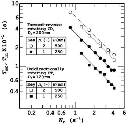
Fig. 7: Relationship between Tm and Nr.
In the figure, the values of mixing time in single impeller system, Tm1, were also plotted for comparison. For both the modes of operation, Tm2 decreased with increase of Nr and there was an inverse relation between Tm2 and Nr (Nienow, 1997). That is, the dimensionless mixing time, Nm, that is the product of the mixing time and impeller rotation rate was almost independent of Nr. For the difference between the dual and single impeller systems, the tendency that Tm2 was on the whole larger than Tm1 was common to the two agitation modes. It was also found that the rate of increase of the mixing time due to increase of the liquid depth was small for the forward-reverse agitation mode compared with that for the unidirectional agitation mode. Figure 8 shows the results of the dimensionless mixing time in dual impeller system, Nm2, and that in single impeller system, Nm1, with variation of the impeller diameter, Di, respectively. Nm2 and Nm1 tended to decrease with increasing Di, but the rate of decreasing differed between the dual and single impeller systems. That is, the dependence of Nm2 on Di was small compared to that of Nm1. This difference suggests that increasing the impeller diameter is not sufficiently effective for decreasing the mixing time in the deep vessel. The mixing characteristics in the deep vessel are significantly affected by the liquid flow between the upper and lower regions within the vessel (Komori and Murakami, 1988; Jahoda and Machon, 1994). In view of this, design taking into consideration the geometry in the axial direction seems reasonable. In other words, for decreased mixing characteristics, by increasing the number of impellers, some improvement may be expected.
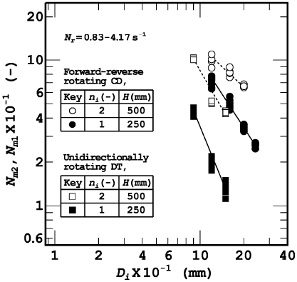
Fig. 8: Relationship between Nm and Di.
Evaluations for the systems where the number of impellers was further increased were then made. Figure 9 shows the relationship between the ratio of dimensionless mixing time in multiple impeller system to that in single impeller system, Nmn/Nm1, and the number of impellers, ni. The impeller clearances in the baffled vessel with unidirectionally rotating triple DTs and that with unidirectionally rotating fourfold DTs are in range where the impellers on the shaft are regarded to act interferingly with each other, with impeller-impeller flow pattern interaction, affecting the power consumption. Under the conditions shown with the dotted line in the figure, further increasing of the mixing time compared to that in dual DT system was observed. On the other hand, it was found that the mixing time in the unbaffled vessel with forward-reverse rotating multiple CDs tended to decrease with increasing ni.
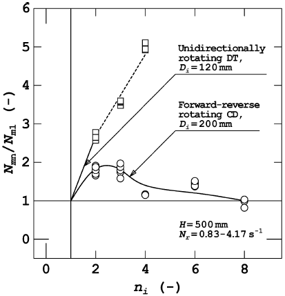
Figure 9. Relationship between Nmn and ni.
The difference in the dependence of mixing time on the number of impellers suggests the difference in the bulk flow pattern within the vessel between the modes of operation. A decreasing of the mixing time is perceived to be due to an increasing of the axial component in the bulk flow to provide larger scale circulating flow field with more whole mixing throughout the vessel. In previous work (Yoshida et al., 2002), it was illustrated that the discharge flow from forward-reverse rotating CD has larger axial component and that the use of impellers in multiple fashion results in a series of discharge flows between the adjacent impellers. The main cause for an improved mixing characteristics of the unbaffled vessel with forward-reverse rotating multiple CDs, namely tendency for the mixing time to decrease with the number of impellers, may be a reflection of the bulk flow with larger axial component.
IV. CONCLUSIONS
Mixing characteristics of liquid phase in an unbaffled vessel containing water with a liquid height-to-diameter ratio of 2 agitated by unsteadily forward-reverse rotating multiple cross type impellers with four delta blades (CDs) were experimentally investigated in comparison with that in a baffled vessel agitated by steadily unidirectionally rotating disk turbine impellers (DTs). For the two modes of operation, the mixing time in the vessel agitated by dual impellers whose arrangement was based on the data of power consumption was larger than that in the vessel with a liquid height-to-diameter ratio of 1 agitated by single impeller. In the vessel with forward-reverse rotating multiple CDs, the mixing time decreased with the number of impellers, contrary to that in the vessel with unidirectionally rotating DTs. Decreased mixing characteristics in the deep vessel were improved by increasing the number of impellers when forward-reverse rotating CDs were used in multiple fashion.
NOMENCLATURE
Cb = off-bottom clearance of the lowest impeller, m
Ci = clearance of impellers, m
Di = impeller diameter, m
Dt = vessel diameter, m
ni = number of impellers, -
Nm = dimensionless mixing time of liquid phase, -
Nm1 = dimensionless mixing time of liquid phase in single impeller system, -
Nm2 = dimensionless mixing time of liquid phase in dual impeller system, -
Nmn = dimensionless mixing time of liquid phase in multiple impeller system, -
Np = impeller power number, -
Np1 = impeller power number in single impeller system, -
Np2 = impeller power number in dual impeller system, -
Npn = impeller power number in multiple impeller system, -
Nr = rotation rate of impeller, s-1
Pm = power consumption of impeller, W
Tm = mixing time of liquid phase, s
Tm1 = mixing time of liquid phase in single impeller system, s
Tm2 = mixing time of liquid phase in dual impeller system, s
Greek letter
ρ = liquid density, kg/m3
REFERENCES
1. Armenante P. M. and G. M. Chang, "Power Consumption in Agitated Vessels Provided with Multiple-Disk Turbines", Ind. Eng. Chem. Res. 37, 284-291 (1998). [ Links ]
2. Armenante P. M., B. Mazzarotta and G. M. Chang, "Power Consumption in Stirred Tanks Provided with Multiple Pitched-Blade Turbines", Ind. Eng. Chem. Res. 38, 2809-2816 (1999). [ Links ]
3. Cronin, D. G., A. W. Nienow and G. W. Moody, "An Experimental Study of Mixing in a Proto-Fermenter Agitated by Dual Rushton Turbines", Food Bioproducts Processing 72, 35-40 (1994). [ Links ]
4. Hudcova, V., V. Machon and A. W. Nienow, "Gas-Liquid Dispersion with Dual Rushton Turbine Impellers", Biotechnol. Bioeng. 34, 617-628 (1989). [ Links ]
5. Jahoda, M. and V. Machon, "Homogenization of Liquids in Tanks Stirred by Multiple Impellers", Chem. Eng. Technol. 17, 95-101 (1994). [ Links ]
6. Kamiwano, M., K. Yamamoto and S. Nagata, "Mixing Performance of Various Agitators", Kagaku Kogaku 31, 365-372 (1967). [ Links ]
7. Komori, S. and Y. Murakami, "Turbulent Mixing in Baffled Stirred Tanks with Vertical-Blade Impellers", AIChE J. 34, 932-937 (1988). [ Links ]
8. Kramers, H., G. M. Baars and W. H. Knoll, "A Comparative Study on the Rate of Mixing in Stirred Tanks", Chem. Eng. Sci. 2, 35-42 (1953). [ Links ]
9. Mochizuki, M., SCEJ ed., Saikin no Kagaku Kogaku 44 Mixing, pp. 76-85, Kagakukogyosha, Tokyo (1992). [ Links ]
10. Nienow, A. W., "On Impeller Circulation and Mixing Effectiveness in the Turbulent Flow Regime", Chem. Eng. Sci. 52, 2557-2565 (1997). [ Links ]
11. Nishikawa M., K. Ashiwake, N. Hashimoto and S. Nagata, "Effect of Impeller Clearance on Power Consumption by Multi-Stage Impellers", Kagaku Kogaku Ronbunshu 2, 426-427 (1976). [ Links ]
12. Shiue, S. J. and C. W. Wong, "Studies on Homogenization Efficiency of Various Agitators in Liquid Blending", Can. J. Chem. Eng. 62, 602-609 (1984). [ Links ]
13. Vasconcelos, J. M. T., S. S. Alves and J. M. Barata, "Mixing in Gas-Liquid Contactors Agitated by Multiple Turbines", Chem. Eng. Sci. 50, 2343-2354 (1995). [ Links ]
14. Yahata, T., K. Ando, F. Komatsu and K. Endoh, "Mixing Region Affected with Turbine Impeller in Stirred Vessel", Kagaku Kogaku Ronbunshu 11, 400-404 (1985). [ Links ]
15. Yoshida, M., A. Kitamura, K. Yamagiwa and A. Ohkawa, "Gas Hold-Up and Volumetric Oxygen Transfer Coefficient in an Aerated Agitated Vessel Without Baffles Having Forward-Reverse Rotating Impellers", Can. J. Chem. Eng. 74, 31-39 (1996). [ Links ]
16. Yoshida, M., A. Ito, K. Yamagiwa, A. Ohkawa, M. Abe, S. Tezura and M. Shimazaki, "Effect of Impeller Clearance on Power Consumption of Unsteadily Forward-Reverse Rotating Multiple Impellers in an Unbaffled Agitation Vessel", Lat. Amer. Appl. Research 32, 189-194 (2002). [ Links ]
Received: April 19, 2002.
Accepted for publication: September 26, 2002.
Recommended by Subject Editor Gregorio Meira.


