


Serviços Personalizados
Journal

Artigo
 Inglês (pdf)
 Artigo em XML
 Referências do artigo
 Enviar este artigo por email
Indicadores
-
 Citado por SciELO
Links relacionados
-
 Similares em
SciELO
Similares em
SciELO
Compartilhar

 Permalink
Latin American applied research
versão impressa ISSN 0327-0793
Lat. Am. appl. res. v.35 n.1 Bahía Blanca jan./mar. 2005
Modeling a fluidized-bed reactor for the catalytic polimerization of ethylene: particle size distribution effects
W. E. Grosso1 and M. G. Chiovetta2
1 INTEC, Univ. Nac. del Litoral-CONICET, 3000 Santa Fe, Argentina,
currently with Praxair Argentina S.A.
2 INTEC, Univ. Nac. del Litoral-CONICET, 3000 Santa Fe, Argentina
mchiove@intec.unl.edu.ar
Abstract ¾ Particle size distributions in the output stream of commercial, fluidized-bed reactors for ethylene polymerization are analyzed using a mathematical model. The impact on the overall reactor performance of the universe of sizes for the particles in the bed, with only a fraction of them being extracted in the product flow, is studied. For the output stream, product size distribution is modeled using both triangular and generalized gamma functions. Extraction system parameters are employed to model the particle quantity and sizes. The importance of the proper modeling of the extraction system is shown through the analysis of the effects several output schemes have on the particle size distribution inside the fluidized-bed. Some of the main reactor variables, such as yield and temperature, are studied for several distributions. Operating variables, such as catalyst feed rate, are varied according to the reactor capacity in a typical, 12 meter bed, 130,000 ton/year reactor. Predictions indicate higher output rates for higher catalyst loads, as expected. A shift towards smaller particle sizes in the product and in the bed is observed when increasing catalyst load. Bed fluidization and heat exchange conditions are shown as affected by size distributions. Results show that it is appropriate to include both product and bed particle diameter distribution when studying the reactor performance.
Keywords¾ Mathematical-Model. Fluidized-Bed. Size-Distribution. Polyethylene. Polymerization.
I. INTRODUCTION
When modeling a polymerization system for the continuous production of polyethylene using a low pressure, catalytic, fluidized-bed reactor of the Union Carbide UNIPOL type (Rhee and Simpson, 1986; Karol et al., 1979; Karol et al., 1981) the particle size distribution is an important issue. A fluidized bed polymerizer contains solid support-catalyst-polymer particles reacting in a bed through which a continuous flow of a gaseous stream composed of monomers and other species is passed. This stream must be maintained at a rate high enough to keep the particle bed in a particular type of suspension referred to as fluidized. The gas leaving the top of the reactor is used as the energy carrier to convey the heat of polymerization out of the reactor. The gas is circulated through gas-liquid, tube-and-shell heat exchangers where it is cooled, to be later recompressed and recycled to the reaction vessel.
The reaction zone is this fluidized particle bed containing a very small fraction of recently added catalyst particles and a large set of growing support-catalyst-polymer particles. Their sizes, which depend on their residence time in the bed, range from the initial support-catalyst particle diameter all the way to the largest particle in the bed, composed mostly of polymer and close to exiting the reactor. The gas flow rate must exceed the minimum fluidization velocity required for the largest particles in the bed. However, gas velocity must be lower than that able to drag the smallest particles with the exiting stream. To achieve this flow regime, high recycle ratios are used, typically of the order of 50. The highly exothermic polymerization reaction is the factor determining the overall, per-pass conversion, generally as low as 2%. The fluidized bed can be visualized as a highly mixed dense phase of particles each of which is moving because of the gas percolation effect. The pressure drop across the reaction zone is equal to, or slightly higher than the weight of the particles divided by the cross sectional area.
Catalyst particles are fed continuously to the reactor zone using an inert gas stream to carry them. The injection point is usually located slightly above the gas distribution plate at the bottom of the reaction vessel, at a height where good mixing conditions exist. Since the catalyst particles are the smallest in the reactor, they are immediately driven upwards. However, while they are being pushed up by the gas flow they are simultaneously increasing their size due to the polymerization. By the time they reach the upper limit of the reaction zone, their terminal velocity is higher than the superficial gas velocity. Thus, particles are kept outside the size range subject to drag and expulsion and become part of the highly mixed fluidized bed.
Product discharge is performed in an discontinuous fashion using a double hatch air-lock system set with tanks and valves as detailed by Aronson (1983). During product discharge, some gas is temporarily taken out of the reactor, and later returned through a recycle. Basically, product extraction is achieved using two separation tanks, exterior to the reactor, as schematically shown in Fig.1. A discharge pipe runs between the bottom portion of the reactor vessel and a separation tank with a locking valve (Fig.1, Ref. 1). A ventilation line links the separation tank top with the upper disengagement portion of the reactor (Ref. 5).

Figure 1. Schematic view of the particle extraction system in a fluidized-bed polymerization reactor.
The separation tank is connected downstream to the transfer tank through a second locking valve (Ref. 2). Gas and solid are passed, opening the proper valves, from the bottom of the reactor to the separation tank. The pressure difference between the bottom and top part of the reactor is enough to drive the gas and the small particles in the separation tank back to the top of the reaction vessel, while the largest particles soon to become the exiting product remain in the separator. Again, operation of the set of valves enables the transfer of these particles from the separation to the transfer tank using both pressure and gravity forces. A gas line (Ref. 4) is available for equalizing pressures when needed. From the transfer tank, the solid is fed to the product processing section (Ref. 3) where particles are chemically and mechanically treated. Stabilizers and additives are mixed with the polymer, and pellets are formed via extrusion and cutting. The catalyst inlet point is located at about 30 % of the diameter of the reaction zone measured from the reactor wall, and below the 25% of the overall height of the reactor zone, measured from the bottom distribution plate. Typical dimensions can be found elsewhere (Grosso, 1999).
Since the product separation system in an industrial reactor operates alternatively opening and closing valve 1 in Fig. 1, particle extraction proceeds in a discontinuous manner. During the time intervals when the separation system is performing size screening and selection operations there is no solid output from the reactor, which behaves temporarily as a semi-batch unit. However, this valve opening/closing sequences are relatively short when compared with particle residence times. From paten literature, cycle times are in the order of 50 seconds, and hence short when compared with residence times between 2 to 3 hours for each particle.
In what follows, the particle size distribution is analyzed in the reaction bed and at the exit flow. Product stream particle size distributions are discussed as well as their impact on the bed particle size distribution behavior. Using a scheme including both distributions and mass and energy balances, the effects of particle size distributions on typical reactor variables are studied.
II. MODELING THE PARTICLE SIZE DISTRIBUTION
A. Fluidized-bed models
The complex system composed of particles and gas in a fluidized-bed has been a matter of extensive studies for many years. Two-phase models such as that of Toomey and Johnstone (1952) were introduced first to account for heat and mass transfer phenomena in fluidized beds. In these schemes, bubbles are considered the dilute phase, while the dense phase is the emulsion formed by particles and interstitial gas. More detailed two-phase schemes can be found in the developments by Davidson and Harrison (1963), Kato and Wen (1969), Werther (1980) and Werther and Hegner (1981). A classical, modified two-phase model with chemical reaction is that of Weimer and Clough (1981) in which the dilute phase, in addition to bubbles, includes the jets above the distribution plate located at the bottom of the reactor. Three-phase schemes, some of them including a particle/gas cloud surrounding the bubble, were presented by Kunii and Levenspiel (1969), Fryer and Potter (1972), Peters et al. (1982) and El-Halwagi and El-Rifai (1988), among others.
The mathematical modeling of fluidized bed reactors for olefin polymerization has the distinctive attribute of a universe of changing particle sizes present at all times. In addition to the usual features in fluidized beds, models must deal with an almost continuous range of ever changing diameters due to polymerization. Specifically in the case of olefin polymerization fluidized beds, the multiple-phase schemes of Choi and Ray (1985), McCauley et al. (1994) and Talbot (1990) are similar to the model developed by Grosso (1999) used in this work to handle the problem of combined heat- and mass-transfer with chemical reaction. As it is shown in the following sections, the difference between previous mathematical schemes and that presented here is the manner in which particle size distributions are modeled.
B. The particle size distribution in the bed
A mathematical model for the polymerization in the fluidized-bed must include a scheme of representation for the particle size distribution within the bed when both the product size distribution and the particle growth within the bed are considered.
Typical previous works, such as those of McCauley et al. (1994), Talbot (1990), and Chen and Saxena (1878) analyze various particle size distributions in the bed without considering the impact of changing the product distribution. In these models, the distribution at the exiting stream is equal to that inside the reactor.
The model in this work introduces the restriction posed on the overall polymerization process by the particle separation system in the discharge chamber. The model recognizes the fact that, in spite of its complexity, the chamber was added precisely to select the larger particles and, hence, to force a given particle distribution at the exit point. As it is shown below, it was found that said distribution is relevant in establishing the properties of the bed and an additional element to adjust the reactor operation. To model the particle distribution function for the particles in the phases of the fluidized-bed polymerization reactor, a scheme similar to that of Talbot (1990) is employed. The three-phase model (bubble, emulsion and cloud) is used to follow the changes suffered by the particles in the bed. Main hypothesis are: a) no particle segregation, fragmentation or agglomeration is considered; b) elutriation is negligible; c) all the catalyst particles entering the reactor are of equal size. The polymerization rate is given by:
Rpr = ks rme wcat W, (1)
where ks is the specific polymerization rate; rme is the monomer density in the emulsion phase; wcat is the catalyst mass fraction in the bed, and W the solid mass in the bed. The reaction rate in the bubble phase is neglected. The particle mass rate of change for any given diameter is:
 | , (2) |
where mp is the particle mass; t is time; rs is the solid density and dp is the diameter for the polymerizing particle. Since no agglomeration is assumed, each particle carries the mass of a single catalyst particle. Because catalyst deactivation is not considerable for the residence times used in an industrial reactor (Estenoz and Chiovetta, 1996a, 1996b), the polymerization rate is approximately constant in each particle, regardless of particle size and age. The rate is:
 | , (3) |
where dcat is the initial catalyst particle diameter, and rcat its density. The equation reflects the fact that the amount of polymer deposited in the particle equals that of the reacted monomer. Combination of Eqs. 2 and 3 renders:
 | . (4) |
Here, the function W encompasses all catalyst- and kinetics-related variables, working as a pseudo kinetic constant to follow the changes in dp as a function of monomer concentration in the emulsion phase of the fluidized-bed (Grosso, 1999):
 | . (5) |
The population balance for the particles in the reactor is:

where Pb is the particle size distribution in the bed and at the reactor outlet, Po the catalyst distribution, Ddp the range in particle size considered, z the integration variable and Qs the product mass rate in the stream exiting the reactor.
For the particular case when the exiting stream is not subject to any restriction with regard to the particle size (no selection of sizes) the distribution at the bed and at the exit are equal, that is Pb = Pq. The resulting distribution function for the bed is:
 | (7) |
This equation is mentioned for reference purposes only, since in what follows, a more realistic particle size distribution function for the exiting stream is added to the population balance.
C. The product distribution
Both the particle size and its distribution for the support-catalyst-polymer exiting the reactor are important parameters in terms of the commercial properties of the product. The latter must undergo processing, chemical and mechanical conditioning, and finishing, prior to their selling as a raw material for transformers. Each of these commercial stages are affected by P and dpa. Product average sizes depend on the particle size distribution which, in turn, is affected by system features such as reactor operating conditions (feed rate, temperature, bed height and diameter), catalyst properties (including its particle size distribution), particle residence time in the reactor, catalyst feeder position in the reactor, product exit position in the reactor, and product separation device. In the population balance in Eq. 6, Pb(dp,t) = Pq(dp,t) was used to obtain the distribution in Eq. 7. This assumption, usual in the literature, implies that product particle size will have the same distribution in the bed and in the product. This is not desired, since a substantial amount of effort is devoted in commercial units, as mentioned in the introductory section, to attain an exiting stream with only the larger sizes. In this manner, only particles showing high catalyst yields will be extracted, keeping the small particles with lower yields inside the reactor.
The reactor separation unit behavior discussed in the paragraph above must be mapped into the model via the introduction of a distribution function for the product particle size. This function is conceptually independent of the bed distribution and related to the nature of the product separation device. Given the selectiveness of the extraction system, a very narrow particle size distribution is expected at the reactor exit.
Generally, the product particle size distribution is mathematically represented employing a triangular distribution function (Valentas and Amundson, 1966; Sundberg, 1979; Kiparissides and Ponnuswamy, 1981; LeBlanc and Fogler, 1987) when modeling several types of reactors. Triangular functions appear as both simple and useful, and can be obtained in a straightforward manner since it is required only the mass of a representative sample, and its largest and smallest sizes, dp2 and dpl, respectively. Since they can be easily and rapidly measured, triangular distributions can be fed to the reactor control system almost on-line.
In a typical distribution, the horizontal, bottom side of the triangle is superimposed to the x-axis of the particle size distribution plot [Fig. 2, Pq(dp) in parts a and b] stretching between the smallest and largest particle diameters dpl and dp2, respectively, in the exiting stream.

Figure 2. Particle size distributions in the exit stream (Pq) and in the fluidized bed (Pb) as functions of the dimensionless particle diameter for a wide triangular function (a) and a narrow triangular function (b).
As shown in the plots (dot lines), a more effective behavior of the separator corresponds to the sharp triangle in the example in Fig. 2.b, with dpl = 30 and dp2 = 35. The closer the values of dpl and dp2, the more efficient the separation. This sharp, tall triangle scheme is close to a Dirac delta function, the limiting theoretical separation where only the particles with the single, largest size are extracted. Because the triangular distribution is not differentiable, analytical functions describing closely a triangular shape are usually employed. Hence, a narrow, generalized gamma distribution function of the Weibull type (Johnson and Kotz, 1970) is proposed for the general expression Pq(dp) = F(dp) in Eq. 6 above:
 | (8) |
The parameter n represents the amplitude of the size distribution, while Xn relates to the average size in the considered product range. The maximum particle size in both the reactor and the exiting stream is dpf = dp2. The expression is directly replaced into the population balance in Eq. 6 to render:
 | (9) |
To solve for the distribution, values for Xn and n are adopted to match the output distribution corresponding to the reactor particle separation device. The most important of those is the average particle size, necessary for stating the reactor fluid dynamics:
 | . (10) |
The lower limit in the integral is the size of the catalyst particle entering the reactor, while the upper limit is the maximum particle size in the product stream. Average particle diameter in the product is given by:
 | . (11) |
The limiting values in the integral are, in general, the same as inside the reactor. The distribution function representing the separation device takes care of the sizes really present in the distribution, as seen above.
A general property cp (such as volume, mass, external surface) applied to any particle in the reactor bed can be averaged to obtain cpa using
 | . (12) |
The average particle properties in the exiting stream can be computed using analogous expressions with Pb(dp) being replaced with Pq(dp) in Eq. 12 above.
III. RESULTS
A. Particle size distributions in the product stream and inside the reactor
The mathematical schemes in Section II are used to model the particle size distributions in a typical ethylene polymerization process, with main reactor parameters listed in Table 1. When applying the equations in the section above, the following hypothesis are made:
1) Catalyst particles are fed to the reactor in a continuous fashion, with a single diameter dcat = 100 µm prior to any polymerization, stating a common initial condition for the size evolution of all particles. The hypothesis is based on the very narrow diameter distribution of the support particles used to manufacture de catalyst and on the specific design of the feeding devices (Calvert and Handwerk, 1973).
2) Catalyst/polymer particles are considered exiting the reactor through the separation device only. Elutriation effects are neglected, and a 100% efficiency is assumed for the separation system (Aronson, 1983).
Table 1. Reactor data

3) Maximum size for any catalyst/polymer particle inside the reactor is that of the maximum allowable size in the separator.
Since the model is solved numerically, both the triangular pattern and the modified gamma function can be used for the simulations. The triangular functions demand extra computational effort to handle the sharp discontinuities at the triangle vertices, but can be processed without instabilities. Fig. 2 shows the effect of using two of these triangular product distributions on the bed particle size pattern. In Fig. 2.a, a loose product separation device is represented with a wide triangle (product particles in the 1000 to 3500 µm size). Save the particles in the 100 to 1000 mm, this permissive separator allows particles with virtually all the sizes in the bed to exit. As a result, the triangular shape in the exiting stream Pq(dp) is copied by Pb(dp), the bed distribution. Because the population balance in the bed is modeled using continuous, differentiable functions, Pb(dp) has rounded ends, instead of the sharp edges in the product distribution. When the restriction in the separator is bounded to the 3000 to 3500 mm range, the picture varies, as shown in Fig. 2.b. Here, the particle size for the maximum of the bed distribution moves toward larger particles. This reflects the importance of properly modeling the separation process. It is clear that with a more stringent separator the model gets closer to the desired reactor operation condition: a narrower distribution of particles is reached in the product stream, with a better utilization of the catalyst. Additionally, a maximum for the distribution closer to the largest particle size in the system is achieved, showing a much better use of the reactor capacity. Both trends compose an indicative picture of the role the separator play in achieving improvement in the utilization of the vessel. If the ideal case of a Dirac delta function were to be considered (a perfect separator extracting only the largest particles from the reactor), the bed distribution will move all the way to the higher sizes, with a sharp, vertical decrease of the distribution at its right end.
When dpl is varied between 2200 and 2800 µm, keeping dp2 constant at 3500 mm, the product distribution triangles and the corresponding bed patterns are shown in Figs. 3, a and b. The higher the product particle diameter as the lower limit in the extraction unit, the narrower the distribution in the product stream, and the higher the particle size at which the maximum of the bed distribution occurs. Since the distributions are normalized, they must show the same area under the curve, and become more slender for narrower separation ranges.

Figure 3. Particle size distributions in (a) the fluidized bed and (b) in the exit stream vs. dimensionless particle diameter. Triangular distributions with minimum sizes of 1000, 2000 and 3000 mm in the product.
When the Weibull gamma function is applied to represent the product size distribution Pq(dp) Figs. 4.a and 4.b show the results for both Pb(dp) in the bed and the originating product size distribution. The curves in Fig. 4.a correspond to the case for which a product distribution with a wide range of diameters, and an average particle size close to that inside the reactor (n = 10, Xn = 2000) are used. Again, save the fraction corresponding to the smaller particles, the output and the bed distributions have the same shape. The predictions for this case are close to those of the models where no physical representation of the particle separator in the output stream is included. The reactor operates with less large particles; consequently, the overall number of particles in the bed is higher, since it is filled with smaller particles. However, this distribution means a good amount of catalyst leaves the reactor having performed poor polymer yields. This type of effect has a direct impact on the productivity and, hence, the economy of the reactor operation.

Figure 4. Particle size distributions in the fluidized bed (Pb) and in the exit stream (Pq) vs. dimensionless particle diameter. Generalized gamma function for the exit stream with n=10, Xn=1000 (a); n=121, Xn=3000 (b).
Fig. 4.b depicts a more realistic case, with n = 121, and Xn = 3000. The product distribution is narrower and the bed distribution shifts to the right as expected. Starting with the triangular distribution in an efficient separator, the particle size range in the exiting stream is bounded between dpl = 2800 mm and dpf = 3200 mm. If a linear average is used for the mean exit particle size Xn = 3000 mm is obtained and the triangular distribution is properly represented by a continuous modified gamma function with n = 121.
To explore the dependency of the results with the parameter n, several situations are searched keeping Xn = 3000 constant, and the results for Pq(dp) and Pb(dp) are depicted in Figs. 5.a and 5.b. The bed shows a sharp decrease at larger diameters in the particle size distribution for the case with the narrower product distribution (n = 121). Smoothers curves are found using lower values, such as n = 16.

Figure 5. Particle size distributions: (a) in the fluidized bed (Pb), and (b) in the product (Pq) vs. dimensionless particle diameter. Generalized gamma function for the exit stream with n=16 and n=121;Xn=3000, both cases.
As a general observation, both the triangular and gamma function represent in an accurate way the product distribution, and both produce similar effects on the distribution in the reactor. Increasing the average particle size in the extractor with either function results in a higher average particle size, with the corresponding decrease in the catalyst mass fraction in the bed. For the gamma function, larger n means narrower product distributions, with higher profiles in the bed distributions.
The simulations conducted verify that a modified gamma function distribution is adequate to mathematically model the triangle distribution that matches the extractor behavior in commercial units. The tandem between the triangular function and the gamma function is convenient in terms of modeling. The former is an accurate and easy to measure in the field means of reflecting the characteristics of the product stream. The latter can straightforwardly match the triangle and, being an analytical tool, is simple to apply in the calculation algorithm.
B. Impact on other reactor variables
The polymerization is affected by the particle size distribution, which is influential in typical reactor variables during polymerization, such as temperature, conversion and yield. The mathematical model of Grosso (1999) for the mass and energy balances in the fluidized-bed reactor, is applied here with the introduction of the generalized gamma function to account for the particle size distribution to analyze the reactor behavior. Particle growth is followed employing the model in Estenoz and Chiovetta (1996a, 1996b). Mass and energy balances, and fluid-mechanic equations, summarized in Tables 2 and 3, are integrated along the reactor height under steady state conditions to produce a calculation algorithm including both the product and bed particle size distributions. The coupling of the equations is performed assuming an average particle size Xn at the exit and performing mass and energy balance to verify the assumption. An iterative numerical scheme is applied until convergence. A set of results from calculations for the reactor in Table 1 are analyzed in what follows.
Table 2. Mass and energy balance equations, for an element in each phase

One of the most important and easily controlled variables in the reactor operation is the amount of catalyst being fed per unit time. The impact of changing the catalyst load is studied, employing the model to predict the reactor behavior with several catalyst feed rates. Conditions were set to obtain relatively high per-pass conversions; hence, the higher temperatures and velocities in the feasible operation window were selected. A temperature To = 333 K and a velocity u0 = 1 m/s for the gas entering the reactor were chosen. To create comparable conditions for each catalyst load, the reactor was set to operate at its maximum bed volume utilization, corresponding to the bed height of 12 m in Table 1.
Table 3. Fluid mechanic correlations for the bed

A set of predictions for the most important reactor variables are listed in Table 4. The corresponding particle size distributions are shown in Figs 6.a and 6.b, where Pb and Pq are displayed, respectively. Three catalyst feed rates (2.55 x 10⁻⁵, 4.37 x 10 and 6.18 x 10⁻⁵ kg/s) are used in the set.
Table 4. Variables for several catalyst feed rates


Figure 6. Particle size distributions: (a) in the fluidized bed (Pb), and (b) in the exit stream (Pq) vs. dimensionless particle diameter for several catalyst feed rates. Reactor parameters as per Table 1.
As seen in Table 4, predictions indicate higher reactor outputs for higher catalyst loads, as expected. From the plots in Fig. 6, a shift towards smaller average particle sizes is observed for higher catalyst loads, both in the bed and in the product stream. The impact of the higher catalyst feed rate is more pronounced on the per-pass conversion than on the average particle size shift. Conversion increases from 1.13% to 2.09% with an almost 85% growth in the range analyzed. Conversely, the average particle size decreases from 2936 to 2680 mm (9% change) in the bed, and from 3696 to 3374 mm (10% decrease) in the product. The increment of per-pass conversion translate directly into a rise in the reactor throughput, which was increased 85% with only a 10% change in particle size.
In terms of reactor tonnage, best results are obtained for smaller particles in the bed and the exit stream, with higher throughput at constant bed volume. This effect is a matter of economical importance, since a trade off situation must be found to balance the higher throughput with a poorer catalyst yield.
Temperature profiles for the solid gas emulsion in the bed corresponding to the predictions in Table 4, are plotted in Fig. 7 as a function of bed height.
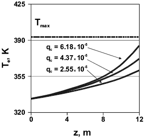
Figure 7. Emulsion phase temperature vs. fluidized-bed height for several catalyst feed rates. Reactor parameters as per Table 1.
The upper limit Tmax for the variable is set at approximately 393 K (120 oC). Following the usual practice in commercial operation, this gas temperature is a theoretical, absolute upper limit before polymer melting occurs. In fact, practical operating conditions are common with an upper value below Tmax since particle agglomeration starts above 383 K and produces heat trans fer and clogging problems. The higher the catalyst flow rate, the higher the thermal load, also contributing to the higher reactor throughput observed. Comparing bed bottom and top, emulsion temperature increases be- tween 28.1 K (qc = 2.55 x 10⁻⁵ kg/s) and 52 K (qc = 6.18 x 10⁻⁵ kg/s) in the catalyst feed rate range analyzed. The curve for qc = 6.18 x 10⁻⁵ kg/s shows that even the upper portion of the bed in the reactor operates well below Tmax, guaranteeing an efficient particle/gas heat transfer.
Calculations were performed to study the effect of the temperature of the gas entering the bed bottom To on the particle size distribution and the reactor behavior. Gas velocity was kept at uo=1 m/s, while the catalyst feed rate was set at 2.55 x 10⁻⁵ kg/s. The bed was operated at its maximum (bed height=12 m). Results are shown in Table 5, in Fig. 8.a and 8.b for Pb and Pq, respectively, and in Figure 9 for the emulsion temperature profile.
Table 5. Variables for several inlet temperatures


Figure 8. Particle size distributions: (a) in the fluidized bed (Pb), and (b) in the exit stream (Pq) vs. dimensionless particle diameter for several inlet gas temperatures. Reactor parameters as per Table 1.

Figure 9. Emulsion phase temperature vs. fluidized-bed height for several inlet gas temperatures. Reactor parameters as per Table 1.
When To is varied between 333 and 353 K throughput increases 46%. With regard to the size distribution, the average particle size both in the bed and in the exit stream increases with temperature. A higher thermal load in the reactor is observed, with higher emulsion temperatures. The curve for qc = 6.18 x 10⁻⁵ kg/s in Fig. 9 shows that starting with T = 353 K at the bottom of the reactor causes the upper portion of the bed to operate above Tmax, predicting unacceptable polymerization conditions. Again, the impact of the recycle gas temperature is more intense on the per pass conversion than on the average particle size shift; reactor throughput increased almost 50% to a corresponding change of only 10% in particle size.
IV. CONCLUSIONS
A mathematical model for a fluidized-bed ethylene polymerizer including particle diameter distributions in the exit stream and in the reactor bed is presented. Particle size distribution representations are considered in the product stream, showing the effect of the separation unit existing in commercial reactors on the properties of the solids in the product stream. When a specific, independent function for the distribution in the outlet is modeled, either by a practical, plant oriented triangular function or by the continuous, differentiable function that represents the triangle, the actual reactor particle size distribution can be modeled.
As they are designed to do, separation devices condition the bed distribution. This, in turn, has a clear impact on the overall reactor performance. The exit distribution can be modeled using a simple triangular mathematical function able to follow the actual product particle diameter and the corresponding sizes in the bed. Results show that the usual assumption of considering the particle size distribution in the output equal to that in the reactor (no separation device included) is of little modeling value and of no economic interest. From the plots, it can be concluded that, in the hypothetical case when the full range of sizes in the reactor is allowed to exit, catalyst particles with very low residence times will be thrown away. Conversely, more realistic calculations can be performed when the particle size distribution in the exit stream is considered independent of that in the bed and established by the separation device. Results also show that the practical triangular function can be analytically integrated using a modified gamma function to the population balances.
Inlet gas reactor temperature and catalyst feed rate must be carefully studied to find the values that ensure that reactor production and utilization are the adequate for the vessel and catalysts used. Typically, it was shown that these two main operating variables (catalyst feed rate and feed gas temperature) must be properly balanced to operate the reactor in conditions such that the full bed height available in the vessel is used. Otherwise, the output stream could show a low yield or be formed by particles with too low a catalyst utilization.
Particle size distribution in the bed plays a critical part in determining the fluidization and heat exchange conditions. Simulations show that it is necessary to include the impact of both the product and bed particle diameter distribution when analyzing reactor performance. Narrow particle distributions in the product render maximum utilization of the reactor volume. Smaller particles in the product stream are predicted when higher catalyst activities are introduced, since the latter imply higher catalyst mass fractions in the bed. Higher activities also produce smaller exiting particles, with less productivity per kg.
These facts suggest the need for an optimization study. A trade off must be searched to balance the optimal use of both the reactor capacity and the catalyst yield.
NOMENCLATURE

Greek letters

Sub/supra indexes

ACKNOWLEDGMENTS
The authors wish to thank Universidad Nacional del Litoral (U.N.L.), Santa Fe, Argentina, and Consejo Nacional de Investigaciones Científicas y Técnicas (CONICET), Argentina, for supporting this work.
REFERENCES
1. Aronson, R., Fluidized bed discharge process, European Patent Application EP 0071430 A2 (1983). [ Links ]
2. Calvert, W. and R. Handwerk, Particulate solids injector apparatus, US Patent 3779712 (1973). [ Links ]
3. Chen, T. and S. Saxena, "A mechanistic model applicable to coal combustion in fluidized beds", A.I.Ch.E. Symposium Series, 176, 149-161 (1978). [ Links ]
4. Choi, K. and W. Ray, "Dynamic behavior of fluidized bed reactors for solid catalyzed gas phase olefin polymerization", Chem. Eng. Sci., 40, 2261-2279 (1985). [ Links ]
5. Darton, R., J. LaNauze, J. Davidson and D. Harrison, "Bubble growth due to coalescence in fluidized beds", Trans. I. Chem. E., 55, 274-283 (1977). [ Links ]
6. Davidson, J. and D. Harrison, Fluidised particles, Cambridge University Press, New York (1963). [ Links ]
7. El-Halwagi, M. and M. El-Rifai, "Mathematical modeling of catalytic fluidized bed reactors - I. The multistage three-phase model", Chem. Eng. Sci., 43, 2477-2489 (1988). [ Links ]
8. Ergun, S., "Fluid flow through packed columns", Chem. Eng. Prog., 48, 89-94 (1952). [ Links ]
9. Estenoz, D.A. and M.G. Chiovetta, "A structural model for the catalytic polymerization of ethylene using chromium catalysts. Part I: description and solution", Polym. Eng. Sci., 36, 2208-2223 (1996a). [ Links ]
10. Estenoz, D.A. and M.G. Chiovetta, "A structural model for the catalytic polymerization of ethylene using chromium catalysts. Part II: thermal effects", Polym. Eng. Sci., 36, 2224-2233 (1996b). [ Links ]
11. Fryer, C. and O. Potter, "Countercurrent backmixing model for fluidized bed catalytic reactors. Applicability of simplified solutions", Ind. Eng. Chem. Fund., 11, 338-352 (1972). [ Links ]
12. Grosso, W., Mathematical modeling of a fluidized bed reactor for the catalytic polymerization of ethylene, Doctoral Dissertation, Universidad Nacional del Litoral, Santa Fe, Argentina (1999). [ Links ]
13. Johnson, N. and S. Kotz, Continuous Univariate Distributions, Houghton Mifflin Publishing Company, Boston (1970). [ Links ]
14. Karol, F., G. Goeke, B. Wagner, W. Frazer, R. Jorgensen and N. Friis, Low pressure preparation of ethylene copolymers in fluid bed reactor and film therefrom, European Patent Application EP 4645 (1979). [ Links ]
15. Karol, F., G. Goeke, B. Wagner, W. Frazer, R. Jorgensen and N. Friis, Ethylene copolymers in fluid bed reactor, US Patent 4302566 A (1981). [ Links ]
16. Kato, K. and C. Wen, "Bubble assemblage model for fluidized bed catalytic reactors", Chem. Eng. Science, 24, 1351-1360 (1969). [ Links ]
17. Kiparissides, C. and S. Ponnuswamy, "Application of population balance equations to latex reactors", Chem. Eng. Com., 10, 283-290 (1981). [ Links ]
18. Kunii, D. and O. Levenspiel, Fluidization Engineering, John Wiley and Sons, New York (1969). [ Links ]
19. LeBlanc, S. and H. Fogler, "Population balance modeling of the dissolution of polydispersed solids: rate limiting regimes", A.I.Ch.E. Journal, 33, 54-63 (1987). [ Links ]
20. Lucas, A., J. Arnoldos, J. Casal and L. Puigjaner, "Improved equation for the calculation of minimum fluidization velocity", Ind. Eng. Chem. Proc. Des. Dev., 25, 426-433 (1986). [ Links ]
21. McAuley, K.B., J.P. Talbot and T.J. Harris, "A comparison of two-phase and well-mixed models for fluidized-bed polyethylene reactors", Chem. Eng. Sci., 49, 2035-2045 (1994). [ Links ]
22. Peters, M., L. Fan and T. Sweeney, "Reactant dynamics in catalytic fluidized bed reactors with flow reversal of gas in the emulsion phase", Chem. Eng. Science, 37, 553-562 (1982). [ Links ]
23. Rhee, S. and L. Simpson, Fluidized bed polymerization reactor, European Patent Application EP 173261 A2 (1986). [ Links ]
24. Sundberg, D., "A quantitative treatment of particle size distributions in emulsion polymerization", Journal of Appl. Pol. Sci., 23, 2197-2205 (1979). [ Links ]
25. Talbot, J.P., The dynamic modeling and particle effects on a fluidized bed polyethylene reactor, Ph.D. Thesis, Queen's University, Kingston, Ontario, Canada (1990). [ Links ]
26. Toomey, R. and H. Johnstone, "Gaseous fluidization of solid particles", Chem. Eng. Prog., 48, 220-237 (1952). [ Links ]
27. Valentas, K. and N. Amundson, "Breakage and coalescence in dispersed phase systems", Ind. Eng. Chem. Fund., 5, 533-542 (1966). [ Links ]
28. Weimer, A. and D. Clough, "Modeling a low pressure steam-oxygen fluidized bed coal gasifying reactor", Chem. Eng. Sci., 36, 549-567 (1981). [ Links ]
29. Werther, J., "Mathematical modeling of fluidized bed reactors", Int. Chem. Eng., 20, 529-540 (1980). [ Links ]
30. Werther, J. and B. Hegner, "Determination of optimum operating conditions of industrial fluidized-bed reactors", Int. Chem. Eng., 21, 585-598 (1981). [ Links ]

