Services on Demand
Journal
Article
Indicators
-
 Cited by SciELO
Related links
-
 Similars in
SciELO
Share
Latin American applied research
Print version ISSN 0327-0793
Lat. Am. appl. res. vol.35 no.3 Bahía Blanca July/Sept. 2005
Analysis of stresses in ADI internal gears mounted with interference: distortion and residual stresses effects
A. D. Sosa1, M. D. Echeverría1 and O. J. Moncada2
1 Grupo Tecnología Mecánica, Facultad de Ingeniería, UNMDP.
adsosa@fi.mdp.edu.ar mechever@fi.mdp.edu.ar
2 Grupo Tecnología Mecánica y División Metalurgia INTEMA, Facultad de Ingeniería, UNMDP.
J.B.Justo 4302, (7600) Mar del Plata, Argentina.
moncada@fi.mdp.edu.ar
Abstract — The stress state in ADI internal gears mounted with interference in aluminum casings is numerically simulated, considering working load as well as circularity distortion (ovalization) and residual stresses resulting from heat treatment. Ovalization exerts the greatest influence on interference and residual stresses, leading to a significantly high compressive stress which does not affect the gear structural integrity due to the high compression strength of ADI. This grants this alloy a competitive edge over steels of similar tensile strength. Still, ovalization has to be minimized considering its unfavorable effect on performance and working load capacity.
Keywords — Stresses State. ADI Internal Gears. Interference Fit. Distortion. Residual Stresses. FEM.
I. INTRODUCTION
The austempered ductile irons (ADI) employed in mechanical parts under severe service demands have probed to yield excellent results, placing these alloys as an alternative material before high-resistance steels (Martínez et al., 1998; Hornung and Hauke, 1984).
The internal gears of the motoreducers planetary system used in freight elevator equipments are an example of an already consolidated industrial application of ADI, which meets the main requirements. However, the microstructural changes produced by heat treatment result in dimensional change (DC), ovalization, tooth profile distortion and residual stresses (Keough, 1991; Moncada and Sikora,1996; Sosa et al., 2001 and Echeverría et al., 2002), anomalies possibly leading to an irregular mechanical assembly operation, to a reduced service life and load capacity. Below, a descriptive synthesis of the studies determining the causes of the already mentioned anomalies as well as the current data available on the subject is presented.
On the one hand, DC alters the interference established by the design for the gear-casing interference fit. However, this effect is largely compensated by the prior correction of machining linear dimensions according to experimental data (Echeverría et al., 2000; 2001), since it allows to predict DC avoiding that machining should be carried out after heat treatment under a unfavorable machinability conditions (Moncada et al., 1998).
Ovalization resulting from non-uniform residual stresses generated by teeth shaping in gear shaping machines (Sosa et al., 2001) and tooth profile distortion are typical defects in this process. Regarding ovalization, it makes gear-casing assembly interference vary along the contour, notoriously increasing towards the oval major axis. As a consequence, interference stress increases (Sosa et al., 2001); though this increase becomes irrelevant if ovalization is minimized by reducing the variation range of machining residual stresses through a strict control of the process (Echeverría et al., 2002).
In turn, austempering heat treatment -by itself- results in residual stresses of little significance for being isothermal cycles of relatively homogeneous phase transformations (Canonico, 1981). Nevertheless, the small and variable wall thickness, characteristic of tubular toothing shapes, promote more distortion than simple and compact shapes, as well as a greater fluctuation of residual stresses, stresses increasing with ovalization (Echeverría et al., 2002).
The stresses state of the gear-casing assembly derives from three sources: working load, interference fit and residual stresses. Total stress should not exceed the admissible value of the material, especially in critical areas where stress is concentrated due to section abrupt changes and small thickness.
Since working load is cyclic, it generates variable stresses within a range, which after interference and residual stresses overlap, can cause fatigue. High mean tensile stresses require the reduction of the admissible range of stresses (Goodman, 1930). However, studies on cast irons (Pomp and Hempel, 1940; Hempel, 1941) and alloyed steels (Ransom, 1954) demonstrated that, under compression, the admissible range increases with mean stress, as long as the maximum stress does not exceed the material compression elastic limit.
An analysis performed on stress fields and deformation by finite elements allows to determine the parameters of greater influence and sensibility, and to establish optimization criteria for geometric and dimensional design as well as for the fabrication process, so avoiding costly experimental trials.
The aim of this work, is to study the influence that ovalization and austempering residual stresses exert on total stress for the minimum interference required, taking into account the working load specified by the manufacturer and parts materials. Besides, the effects of toothing and casing geometry on interference stress are also evaluated.
II. EXPERIMENTAL PROCEDURE
A. Material
Twelve assemblies, made up of an ADI internal gear mounted with interference in an aluminum casing were employed.
Gears are industrially manufactured from cast tubes of pearlitic ductile iron. Their chemical composition is shown in Table 1. The tubes were machined by a straight internal and external turning and by teeth shaping in a gear shaping machine (Fellows system).
Table 1. Chemical composition [wt%] of gears

ADI thermal cycle consisted in austenitizing the parts at 910oC during 1hour, and later austempering them in a salt bath at 310oC during 2 hours, to obtain ADI grade 3 (ASTM A897-M90). The mechanical properties are: Tensile Strength = 1200 MPa; Yield strength = 850MPa; Elongation = 4%; Elasticity modulus = 170000 MPa; Shear modulus = 158000 MPa; Poisson's ratio = 0.28.
The gears have 45 teeth, module 2, pressure angle 20o, and their dimensions are shown in Fig. 1.

Figure 1.Dimensions of the gears
The gear is mounted with interference on the casing in order to assure concentricity. The minimum interference value established by design is of 0.05 mm. Mounting is performed by contraction, expanding the casing by heating. A cotter is employed in the gear-casing coupling to assure the transmission of the torque required during service.
The internal gear-casing assembly is part of a four-stage planetary motoreducer of 5 satellite gears per stage, so obtaining a final reduction of 256:1. Taking into consideration the number of satellites and the contact ratio (3), it turns out that the 1900 Nm nominal torque specified by the manufacturer is distributed along the 15 teeth of the internal gear. Figure 2 schematically shows the components of one of the stages of the motoreducer.
B. Dimensional Metrology
The ovalization produced during austempering as well as the contraction generated by the mounting with interference on the casing is determined for each gear by means of a CMM (coordinate measuring machine). Minimum and maximum gear ovalization values and their corresponding contractions are listed in Table 2.

Figure 2. Components of one of the motoreducer stages.
Table 2. Ovalization and contraction values of gears

The ovalization ΔR (shape distortion) is the difference between Rc and Ri radii of the circumscribed and inscribed circles of the distorted contour, respectively. Figure 3 schematically shows the distorted contour.

Figure 3. Schematic diagram of distorted contour. (ΔR: Ovalización, Rc: circumscribed circle radius, Ri: inscribed circle radius)
Radial contraction is calculated as the difference between the gear interior mean radii before and after mounting.
Residual stress values measured by means of X-ray diffraction in different positions along the contour in areas near the root land of the teeth are shown and analyzed under Results and Discussion section.
C. Stresses Simulation
With the aim of analyzing ovalization influence and the distinctive features of interference fit, such as casing and gear geometry and materials, on stresses state, a different model is developed for each case by means of finite elements analysis.
The first step is to determine the thickness of an equivalent ring, which under uniform external pressure suffers the same contraction as the gear under identical load. When adopting a pressure value producing a contraction equal to that experimented by mounting the gear (Table 2), a 4.82mm thickness is obtained. Besides, the thickness of a uniform section casing of identical actual casing mass is also determined, being of 10.7mm.
The following step is to develop different models to simulate the interference fit between:
The uniform casing and the equivalent ring (Fig. 4a)
The uniform casing and the circular gear (Fig. 4b)
The uniform casing and the oval gear (ΔR=0.12 mm)
The actual casing and the equivalent ring (Fig. 4c)
The actual casing and the oval gear (ΔR=0.04/0.08/0.12 mm) (Fig. 4d)
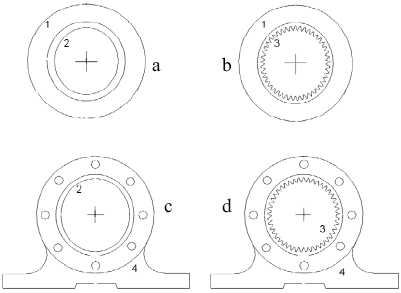
Figure 4. Assemblies analyzed by FEM. (1)Uniform casing (2) Equivalent ring (3) Gear (4) Actual casing.
In all cases, a plane stress state is considered (σz = τzy = τxz = 0) according to the elastic lineal model.
In the modelling, finite elements of 3 nodes were employed, using an adaptive mesh for the gear, which allowed to obtain solutions with errors of less than 0.05%.
All meshes were designed so that contact nodes were confronted in the same radial direction at an interference distance (k). The used algorithm handles node-node contact by means of appropriate constraint equations such as (I) and (II) that restrict nodes contact displacement until reaching the same final position.
For radial direction ρ : Uρ(i) - Uρ(j) = k. (1)
For tangential direction  : U
: U (i) - U
 (j) = 0. (2)
Where Uρ(i) and Uρ(j) are i, j nodes displacement in a direction ρ; U (i) are U
 (j) i,j nodes displacement in a direction
  .
.
By means of an iterative process employing a macro until reaching convergence, nodes contact are radially uncoupled when normal stress (σn) is tensile; and tangentially when shear stress is above μ . σn(i). Where μ is the coefficient of friction.
For each model, maximum effective stresses (von Mises) resulting from interference and working load are determined. When residual stresses are contemplated, total effective stress is obtained.
Taking into account that the rotation velocity is of »5 rpm and that contact is gradual, load application is considered quasi-static.
The expression used to obtain the maximum effective stress is:
 | , (3) |
where σx and σy are normal stresses (radial and circumferential, respectively) and τxy the shear stress in the xy plane.
III. RESULTS AND DISCUSSION
Gear total stress results from the stresses overlap due to gear-casing interference fit, working load and residual stresses. Each of them is analyzed separately.
A. Stresses due to gear-casing interference fit
To begin with, the influences exerted by toothing geometry, ovalization and casing geometry on stresses state are separately analyzed by means of models which only contemplate interference. In all cases, normal stresses were compressive with their maximums placed in the tooth fillet, where root land and profile teeth are connected (fig. 5). Table 3 lists the maximum effective stress values (von Mises) for each model, with their corresponding interference values.
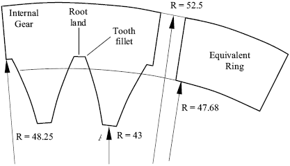
Figure 5. Radius of the gear and their equivalent ring
Table 3. Maximum effective stress values (von Mises) in the interference fit.
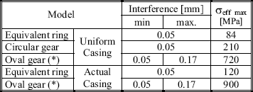
(*) Maximum ovalization value (ΔR=0.12 mm)
Error between the FEM and analytical solution for equivalent ring - uniform casing assembly was less than 0.004%. Error between the FEM and experimental results for actual casing and the oval gear assembly will be discussed in item A.3.
A.1. Toothing Influence
For the uniform casing, the values in Table 3 allow to compare the maximum effective stresses of the circular gear and its equivalent ring whose dimensions are shown in Fig. 5.
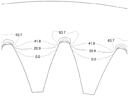
Figure 6. Effective stress contours [Mpa] due to circular gear - uniform casing interference fit.

Figure 7. Effective stress contours [Mpa] due to circular gear - uniform casing interference fit. Amplified view of tooth fillet.
It can be concluded that the stress is notoriously greater in the gear, and encompasses a thin superficial layer located in the tooth fillet as shown by the stresses contour for a portion of the circular gear (Fig. 6) as well as by the amplified tooth profile (Fig.7). All models show similar stress contours shape with different values.
For positions located in the major radii, stress decreases exponentially until reaching the ring value at a depth of about 1 mm (Fig. 8), demonstrating that the section abrupt variations -typical of toothing- act as stress concentrators.

Figure 8. Effective stresses (von Mises) for different radial positions, from tooth fillet towards external contour.
A.2 Ovalization influence
The effective stress on the oval gear varies along the contour since interference also does. This leads to different contractions in each point, which tends to gear rounding off, increasing the radius of curvature on the oval major axis and reducing it on the minor axis. As a consequence, tensile stresses reducing interference stress appear on the major axis. Whereas on the minor axis, compression stresses do, increasing interference stress. Figure 9 shows the displacement of the gear external contour points when mounted on a uniform casing, denoting -at an expanded scale- the rounding off effect, which is consistent with those experimentally observed for the actual gear-casing assembly.

Figure 9. Displacement of the oval gear external contour points during uniform casing fitting (expanded scale).
Table 3 shows, for the most ovalized gear and uniform casing, the maximum effective stress value, which is located near the oval minor axis. It can be noticed that the stress triples in relation to the circular gear, due to interference increase, demonstrating the notorious influence exerted by ovalization.
A.3. Casing geometry influence
For the interference fit between the actual casing and the equivalent ring, Fig. 10 shows that the stress varies due to casing discontinuities, reaching their maximum values in the areas next to the holes. This demonstrates that the casing exerts a variable stress leading to also variable deformations along the ring contour.
If the most ovalized gear mounted on actual casing is considered, the effective stress increases with respect to the uniform casing (see Table 3), and the maximum value is found near the holes, and also in oval minor axis.
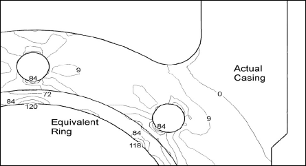
Figure 10. Effective stress contours [Mpa] due to equivalent ring-actual casing interference fit.
The ovalization, contraction and displacement values calculated by FEM as well as those experimentally obtained are shown in Table 4. The approximate 10% error is attributed to simplifications of material properties and parts surface texture.
Table 4. Experimental and FEM results [mm] for an oval gear (*) and actual casing assembly.

(*) For gear with ΔR=0.12mm, before mounting
A.4. Combined influence of toothing, ovalization and actual casing geometry on interference stresses
Considering the maximum effective stress values listed in Table 3, it is evident that the factor that mostly affects the stress resulting from interference is ovalization.
Furthermore, considering the overlapping effects of toothing, ovalization and the geometry of the actual casing, it can be concluded that the maximum effective stress resulting from interference is notoriously elevated, and it is located in the tooth fillet near the oval minor axis. Their values, presented as a function of ovalization, are graphically shown in Fig. 11, and its influence on total stress is analyzed under item D.
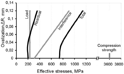
Figure 11. Maximum effective values of interference, load, and total stresses, and minimum effective residual stresses for different ovalizations.
B. Residual stresses
Austempering residual stresses are shown in Fig. 12. These are compressive and increase with ovalization, vary along the contour and their minimums are placed in the oval minor axis (2-4), where interference stress is maximum. Minimum effective residual stress values for different ovalizations are graphically shown in Fig. 11.

Figure 12. Residual stresses in ADI gears (radial direction)
C. Stresses due to working loads
The maximum stress resulting from working load is placed in the tooth fillet and has an opposite sign at each side of the tooth as shown in Fig. 13. Therefore, in the tensile side, its value has to be deducted from that of residual and interference stresses, both compressive, resulting in a stress lower than that corresponding to the opposite side.
Figure 11 shows that maximum effective stresses resulting from the working load are independent of ovalization.
The cyclic characteristic of working load stresses is dealt when total stress is analyzed under item D.

Figure 13. Location and sign of load maximum stresses.
D. Total Stress
Figure 11 shows, for different ovalization values, the maximum effective values of the total stress corresponding to the oval minor axis of the tooth compressed side, coincidental with both maximum interference and minimum residual stresses.
It should be noticed that the stress resulting from interference is the one that most influences total stress magnitude, while that resulting from the load is comparatively low, constituting a distinctive trait of planetary reduction systems.
Taking into account that the resulting stress is compressive, and that the compression strength σC of free-graphite cast irons triples tensile strength σT (Angus, 1976), being for ADI is σC » 3σT = 3600 Mpa, the effective total stress for the most ovalized gear is approximately 30% of that value (Fig. 11). This implies a safety margin in accordance with the classic criteria of dimensioning. However, it is advisable to minimize ovalization, in order to reduce interference stress and residual stresses, so as to attain a greater load capacity in the motoreducer. Figure 11 shows that total stress slightly increases in ovalization values of up to ΔR=0.04. For greater values the increase is substantial.
Besides, it was determined that total stress alternatively varies in an approximate range of 350 Mpa because working load is cyclic. Taking into account that the stresses state is compressive and that its variation range is low in relation to material compression strength, failures are improbable.
This stresses state is more favorable for ADI than for steels of similar σT value, because of its greater compression strength (σC » 3σT for ADI and σC » σT for steels). Other favorable aspects of ADI are its cost and the strength/weight ratio.
IV. CONCLUSSIONS
During stresses analysis of ADI internal gears mounted with interference in aluminum casings, it was determined that the ovalization produced during heat treatment is the factor of greater influence due to its effect on interference and residual stresses. These stresses, as well as working load stresses, result in a compressive total stress, varying along the contour, which increases with ovalization.
For the analyzed ovalization values, the gear structural integrity is affected neither by the maximum total stress nor by the stress variation range generated during the load cycle, due to the high material compression strength. Still, ovalization has to be minimized considering its unfavorable effect on performance and loading capacity of the mechanical assembly.
The compressive stress state allows to take advantage of the greater compression strength that ADI has over steels of similar tensile strength.
Acknowledgements
The authors thank to Professor J. Sikora for the constructive discussions that contributed to the present work and to Mancuso S.A. for the provision of the studied material.
REFERENCES
1. Angus, H., "Cast Iron: Physical and Engineering properties", Butterworths, London, I, 46-47 (1976). [ Links ]
2. Canonico, D., Metals Handbook, Heat Treating, Ninth Edition, ASM International, 4, 3-5 (1981). [ Links ]
3. Echeverría, M., O. Moncada and J. Sikora, "Efectos de las tensiones residuales generadas por mecanizado y tratamiento térmico en engranajes de ADI", Actas CONAMET/SAM Simposio Materia 2002, Santiago de Chile, I, 281-286 (2002). [ Links ]
4. Echeverría, M., O. Moncada and J. Sikora, "Corrección de Cotas de Mecanizado debidas a la Variación Dimensional en piezas de ADI aplicadas a una producción en serie de Engranajes" , Jornadas SAM 2000, IV Coloquio Latinoamericano de Fractura y Fatiga, Neuquén, Argentina, 405-412 (2000). [ Links ]
5. Echeverría, M., O. Moncada and J. Sikora, "Influence of the Dimensional Change, and its Dispersion, on the Fabrication Size Tolerances of ADI Parts: Comparison with SAE 4140 Steel", ISIJ International, 41, 25-30 (2001). [ Links ]
6. Goodman, J., "Mechanics Applied to Engineering", 9th ed., Longmans, Green & Co., Inc., New York(1930). [ Links ]
7. Hempel, M., Zeitschrift des Vereines Deutscher Ingeneure, 85, 290-292 (1941). [ Links ]
8. Hornung, H. and W. Hauke, "Austempered Ductile Iron, a Material for Gears", 1st. International Conference of ADI, 185-213 (1984). [ Links ]
9. Keough, J., "The Development, Processing and Application of Austempered Ductile Iron", Proc. of the 3rd World Conf. on ADI, AFS Trans., Illinois, II, 638-658 (1991). [ Links ]
10. Martínez, R., R. Boeri and J. Sikora, "Impact and Fracture Properties of ADI, Comparison with SAE 4141 Steel", AFS Transactions, 98-08, 28-30 (1998). [ Links ]
11. Moncada, O., R. Spicacci and J. Sikora, "Machinability of Austempered Ductile Iron", AFS Transactions, 106, 39-46 (1998). [ Links ]
12. Moncada, O. and J. Sikora, "Dimensional Change in Austempered Ductile Iron", AFS Transactions, 104, 577-580 (1996). [ Links ]
13. Pomp, A. and M. Hempel, Mitteilungen aus dem Kaiser Wilhelm Institut für Eisenforschung, 22-11, 169-201 (1940). [ Links ]
14. Ransom, J., Discussion in Proceeding. ASTM, 54, 847-848 (1954). [ Links ]
15. Sosa, A., M. Echeverría, O. Moncada and J. Sikora, "Efectos del mecanizado y de una ferritización previa sobre la distorsión y variación dimensional en engranajes de ADI", Jornadas SAM - Conamet - AAS. Posadas, Argentina, 475-484 (2001). [ Links ]


