


Services on Demand
Journal

Article
 English (pdf)
 Article in xml format
 Article references
 Send this article by e-mail
Indicators
-
 Cited by SciELO
Related links
-
 Similars in
SciELO
Similars in
SciELO
Share

 Permalink
Latin American applied research
Print version ISSN 0327-0793
Lat. Am. appl. res. vol.37 no.3 Bahía Blanca July 2007
Test of nuclear-pulse shapers using oscillation-based test
G. Peretti1, E. Romero1 and C. Marqués2
1 Grupo de Investigación y Servicios en Electrónica y Control, Facultad Regional Villa María, Univ. Tecnológica Nacional, 5900 Villa María, Argentina
gisec@frvm.utn.edu.ar
2 Grupo de Desarrollo Electrónico e Instrumental, Facultad de Matemática, Astronomía y Física, Univ. Nacional de Córdoba, 5000 Córdoba, Argentina
marques@famaf.unc.edu.ar
Abstract — This paper addresses the problem of testing continuous-time nuclear-pulse shapers using Oscillation-Based Test (OBT). The proposal is to convert the whole systems into non-linear oscillators, avoiding the partition in low-order sections. The design of the oscillators is very simple because the non-linear elements are mathematically modeled using the describing function approach, and the study of the oscillators is made using techniques of linear systems. The test strategy presents high fault coverage and requires only one test session. The last characteristic allows reducing the time required for executing the test and the complexity of the test controller. The OBT schemes are validated using deviation and catastrophic fault models.
Keywords — Oscillation-Based Test. Nuclear Pulse Shaper. Testing.
I. INTRODUCTION
Nuclear pulse shapers are used for ionizing radiation spectroscopy usually associated with Multi-Channel Analyzers (MCA) in order to obtain the spectra of the radiation field under study.
The block diagram of a typical radiation spectroscopy system is presented in Fig. 1. In the figure, a preamplifier amplifies the charge signal, Qδ(t), delivered by the detector. The shaper processes the preamplifier output and an Analog to Digital Converter (ADC) converts the shaped signal to the digital domain. Finally, the MCA obtains an energy histogram.
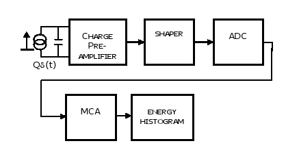
Figure 1. Radiation spectroscopy system. Block diagram.
Convenient conditions for spectroscopy applications are achieved when the pulse delivered by the shaper is Gaussian or semi-Gaussian (Knoll, 2000). There are several ways for implementing Gaussian shapers, but an extended and very simple alternative is by means of connecting a differentiator in cascade with several integrators. For this kind of topologies, the approximation to the Gaussian pulse-shape improves as the number of integrators in the cascade increases. In practice, configurations with two up to six integrators are employed.
Despite the fact that nuclear pulse shapers are widely used in the nuclear industry and in basic and applied research, the problem of testing them remains unexplored. In this paper, a simple and efficient test solution is proposed for continuous-time pulse shapers, using a particular test strategy named Oscillation-Based Test (OBT).
OBT has been proposed for the first time by Arabi and Kaminska (1996) as a test strategy able to detect commonly observed defects in the manufacturing process. However, the circuit resources added to the original system for testing can be re-used for implementing periodic test during the in-field operation. This kind of test is particularly important for portable and critical applications demanding a high degree of confidence in the circuit.
II. PREVIOUS WORK ON OBT
The core idea in OBT is the conversion of the Circuit under Test (CUT) into an oscillator, adding some extra components to force the circuit to oscillate. It is assumed that a fault in the CUT will produce deviations in the frequency or in the amplitude and consequently it will become observable (Arabi and Kaminska, 1996). Some of the reasons that make this approach very attractive are: its concept is very simple; it avoids the need of resources for stimulus generation and application and it requires relatively simple measurements. These characteristics allow the application of this strategy in Built-In Self-Test (BIST) structures.
OBT has been successfully applied to a number of analog and mixed-signal circuits. At this point, it is necessary to remark that nuclear-pulse shapers are a special kind of filters optimized for Gaussian response to step inputs. For this reason, the attention is focused on previous work related to the application of OBT to filters.
The test of several types of continuous-time filters by OBT is reported by Santo et al. (1997), Arabi and Kaminska (1999) and Wong (2000). An important group of papers has also been devoted to study the application of OBT to Switched-Capacitor (SC) filters (Huertas et al., 1999, 2000, 2002a; Kac and Novak, 2004) and the guidelines established by the authors could be extended to continuous-time filters and consequently to the circuit addressed in this paper.
In the above-referenced papers, all CUTs are low-order filters. This characteristic allows the mathematical modeling of the oscillators and extracting the analytical expressions for the oscillation parameters. Huertas et al., (1999) address the test of high-order filters, applying the "divide and conquer" principle for partitioning the filter in low-order sections. In this way, the testing problem is reduced to a sequentially implemented test of low-order sections. Huertas et al. (2002b, 2003) also apply this principle for testing Sigma-Delta modulators. Additionally, they propose a set of changes in the original system for obtaining a low-pass characteristic. In this way, it is possible to use the Describing Function Approach (DFA) for the mathematical modeling of the oscillators.
Recently, several authors reported the application of OBT to filters for which the partition in low-order sections is not possible. Particularly, Romero et al. (2005) target the test of third-order SC ladder filters. The good results obtained motivated the extension of the strategy to higher-order filters (Peretti et al., 2005). Although the authors of these papers have shown that the application of OBT to this kind of systems is feasible, the results should be considered valid only for SC ladder topologies. There is no evidence that the application to other ladder filters implementations like RC or Gm-C will be successful.
In this paper, the partition of the shaper in low-order sections is intentionally avoided, with the aim of maintaining a low intrusion in the original system. This allows low performance degradation in normal mode due to the reduced complexity of the circuits to be added for implementing the test. By other way, the circuits are not modified for obtaining the best conditions for the application of DFA. In this sense, it is assumed that this method is only an approximation, allowing a rapid "first cut" design of the oscillators that have to be validated by simulations. Additionally, it is proposed a graphical methodology for analyzing the oscillators because the high order of the resulting expressions complicates the analytical handling.
III. CIRCUITS UNDER TEST
Figures 2 and 3 show the three-integrator and four-integrator shaper configurations adopted as cases of study. In these figures, the first section introduces a zero and a pole in the global transfer-function and the remaining sections introduce only a pole each. The last amplifier in the cascade is designed for obtaining unity gain for unity-step input and for providing inversion if it is necessary. The values of the circuit parameters are reported in Table 1.
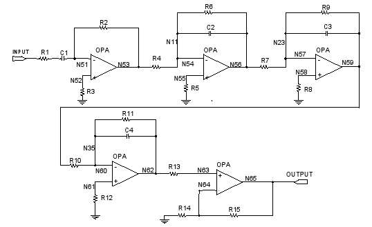
Figure 2. Three-integrator shaper.
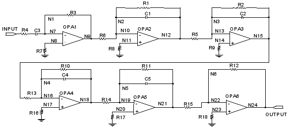
Figure 3. Four-integrator shaper.
Table 1. Circuit parameters.
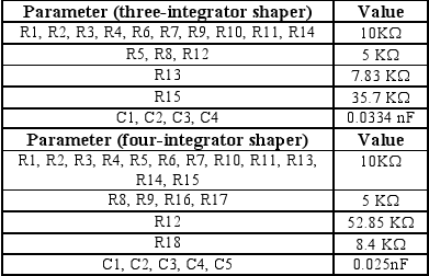
For implementing the shapers, the OPA656 operational amplifier is used. Figures 4 and 5 show the step responses of the three and four integrator shapers, obtained by SPICE simulations using the simulation models provided by the vendor.
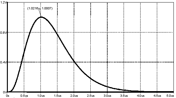
Figure 4. Three-integrator shaper. Step response.
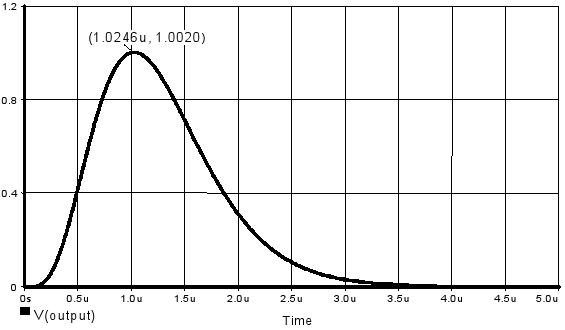
Figure 5. Four-integrator shaper. Step response.
IV. OBT IMPLEMENTATION
As it was previously stated in this paper, the whole filters are converted into oscillators. In this way, only the input and the main output are manipulated to switch the circuit from normal to test mode, as it is illustrated in Fig. 6. In test mode, the CUT (shaper) is isolated from the rest of the circuit by means of S1 and S4 switches, while S2 and S3 connect the feedback path for forcing the oscillations. In normal mode, S1 and S4 remain closed and S2 and S3 are open.
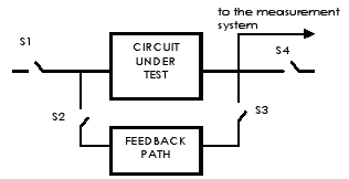
Figure 6. Oscillator implementation.
For implementing OBT it is adopted a scheme that uses a non-linear circuit in the feedback path. The principle of the oscillator and the characteristic of the non-linear circuit are both depicted in Fig. 7. The advantages of this kind of oscillators for implementing OBT are widely explained by Huertas et al. (1999, 2000, 2002a).
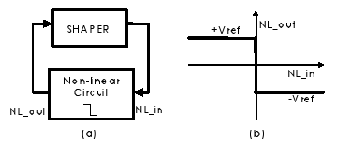
Figure 7. Proposed OBT scheme (a) and non-linear circuit characteristic (b).
It should be mentioned that the non-linear circuit could be easily implemented by adopting the scheme depicted in Fig. 8. The comparator drives the analog switches SW1 and SW2 and obtains +Vref or -Vref at the output of the non-linear circuit, depending on the polarity of the signal delivered by the CUT.
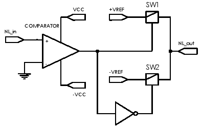
Figure 8. Non-linear circuit implementation.
Regarding the OBT implementation details, the adequate selection of the switches present in the OBT scheme (Fig. 6) is very important, because they provide the programmability of the structure, allowing the test. However, these switches can affect the performance of the system in normal mode.
The main characteristics of these switches are their "on" and "off" resistances, named Ron and Roff respectively. The values of these parameters have to be carefully selected, depending on the point where they are to be inserted. For the cases under study, the most critical switch is S1. It is connected to the input of the shaper and is part of the signal path in normal mode. For this switch, Ron has to be negligible when compared with R1 (three-integrator shaper, Fig. 2) or R4 (four-integrator shaper, Fig. 3) in order to avoid affecting the time constants of the first stage of the shapers. Similar consideration has to be taken into account for S2, due to for this switch Ron affects the oscillation condition. S3 connects the output of the shaper under test to the high input impedance of the comparator (non-linear element, Fig. 8); consequently, Ron is not critical for S3. Finally, S4 is used for connecting the output of the shaper to the ADC input (Fig. 1). If the ADC has high input impedance, then Ron parameter is not critical for S4. For all the switches, the parameter Roff has to be as high as possible in order to provide an effective isolation.
An alternative for implementing the NL circuit is by using a logical inverter (or a couple of inverters if inversion is not necessary) as proposed Arabi and Kaminska (1999). In this case, it is necessary to adjust the supply voltages of the inverters in order to obtain the required Vref.
V. ANALYSIS OF THE OSCILLATION CONDITIONS
DFA is adopted for the mathematical modeling of the non-linear elements present in the circuits. This approach allows using tools employed for linear systems analysis, reducing the complexity of the study.
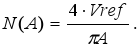
Using DFA it is possible to model the non-linear element transfer function as an equivalent gain N(A). For the abrupt non-linear characteristic of Fig. 7(b), this gain is proportional to the extreme values (Vref) and inversely proportional to the amplitude (A) of the signal at the output of the shaper (NL_in ):
 | (1) |
The full analysis for obtaining (1) can be found in the literature (Gibson, 1963).
Due to the high order of the involved transfer functions, the oscillation conditions are determined from the AC analysis available in SPICE. In this way, it is possible to achieve a straightforward design of the oscillators.
The oscillation can be forced at the frequencies for which the system frequency response presents a phase-shift multiple of π. At these frequencies, the inverse of the filter transfer-function module is the required gain, or the value of the describing function N(A) implemented by the non-linear element. The oscillation amplitude is obtained making this value equal to (1). The oscillation frequency is directly obtained from the Bode plots.
The three-integrator shaper frequency response is band-pass type as can be observed in Fig. 9. Two different oscillation conditions are possible for this circuit. One of them (Mode1) is located at 1.078 MHz and requires a gain of 11.258db. The other one occurs at 196.112 KHz with a required gain of -2.528db (Mode2). In the figure, the arrows show the points where the oscillation condition is fulfilled, and it is indicated the value (frequency, filter transfer-function module) for the two modes. The establishment of a particular oscillation mode depends on the sign of the non-linear feedback path.
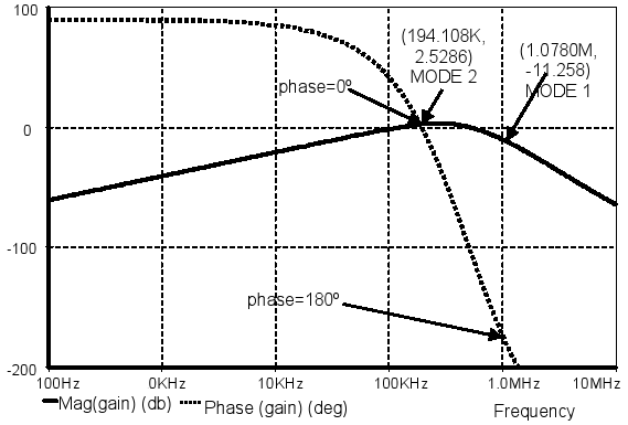
Figure 9. Three-integrator shaper. Frequency response.
It should be mentioned that under test conditions, the signal at the shaper input is square due to the characteristic of the non-linear element used for forcing the oscillations. The spectral purity of the oscillator output is related to the ability of the shaper for attenuating the high-order harmonics of the input signal. When Mode1 is established, these harmonics are considerably attenuated and the output is almost sinusoidal. The situation is quite different for Mode2 due to several harmonics are not attenuated and consequently, the output signal considerably departs from the sinusoidal shape. The waveforms obtained in Mode1 and Mode2 are depicted in Figs. 10 and 11 respectively.
Figure 10. Three-integrator shaper. Mode 1 output signal.
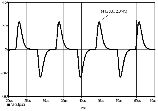
Figure 11. Three-integrator shaper. Mode 2 output signal.
The four-integrator shaper frequency response is reported in Fig. 12. In the figure it is observed that there are two limit-cycle conditions located at 839.46KHz with a required gain of 5.32dB (Mode1) and 203.28KHz with a gain of -2.13dB (Mode2). Due to the previously stated considerations for the three-integrator shaper, only the Mode1 oscillation is sinusoidal. The waveforms obtained from both oscillation modes are depicted in Figs. 13 and 14.

Figure 12. Four-integrator shaper. Frequency response.

Figure 13. Four-integrator shaper. Mode 1 output signal.
Figure 14. Four-integrator shaper. Mode 2 output signal.
It should be mentioned that for both shapers, the conditions required for applying DFA are completely fulfilled only for Mode1. Despite this fact, we remark that the use of DFA has allowed the prediction of the limit-cycle conditions, but with considerable errors in the estimated oscillation parameters for Mode2. Consequently, the use of this simple and appealing tool requires the validation of the oscillators by simulation (Huertas, 2004). Other tools can be used for the analysis (Pavan and Tsividis, 1998), but require a cumbersome methodology for the oscillators design.
The amplitude and frequency predicted by the proposed graphical-analytical method (T), the obtained ones from circuit simulations (S) and the corresponding errors (T-S) are reported in Table 2. Vref is settled to 2.9V for both shapers. As previously stated, the errors for oscillations in Mode1 are negligible.
Table 2. Oscillation parameters and errors.
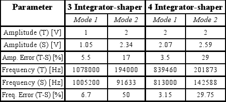
Mode1 is selected for implementing OBT, due to the better spectral purity of the resulting signals. Additionally, the accuracy of the predictions using DFA allows changing the test conditions (by altering the values of Vref) and determining the oscillation conditions in a simple way.
VI. FAULT INJECTION IN THE PASSIVE COMPONENTS
Two fault models are adopted for performing the evaluation of the OBT schemes: single deviation-fault and single catastrophic-fault (short and open circuits) in the passive components of the shapers. Additionally, the open-circuit fault-injection procedure is extended for covering all the circuit nodes. This is equivalent to take into account all possible open circuit faults (Roh and Abraham, 2003).
The deviation-fault injection procedure suggested by Huertas et al. (1999) is adopted in this paper with the aim of obtaining comparable metrics. Particularly, we inject faults of +50%, +20%, -20% and -50% in all the circuit parameters. In this study, it is assumed that a fault is detected if it produces a 5% deviation in the frequency or amplitude of the oscillations. This detection threshold is arbitrary and can be modified if the precision of the frequency and amplitude measurement systems is improved (Wong, 2000; Romero et al., 2004, 2005; Peretti et al., 2005).
VII. FAULT SIMULATION RESULTS
A. Three-integrator shaper
A total of 57 catastrophic-faults have been injected in the three-integrator shaper and all of them were detected, resulting in fault coverage of 100%. Additionally, 76 single deviation-faults have been injected in the circuit parameters, obtaining an optimal coverage of 100%. The nomenclature adopted for the injected faults is reported in Table 3.
Table 3. Nomenclature adopted for the injected faults.

In Table 4 are depicted the catastrophic-fault simulation results for the three-integrator shaper. From this table, we conclude that it is possible to obtain 100% of catastrophic fault coverage by implementing only amplitude measurements. It should be highlighted that only the faults producing an oscillating output have been included in the tables reporting the fault simulation results.
Table 4. Catastrophic-fault simulation results. Three-integrator shaper.

The deviation-fault simulation results are depicted in Tables 5 and 6. From these results, it is also possible to conclude that fault coverage of 100% can be achieved only by amplitude measurements. As a result, only the circuit for amplitude measurement is required. This is a very important issue from the test viewpoint due to both the circuital resources and the time required for performing the test are reduced.
Table 5. Deviation-fault simulation results. Three-integrator shaper.
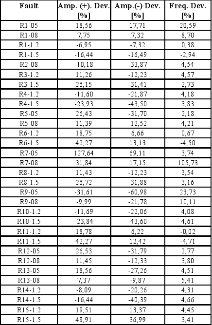
Table 6. Deviation-fault simulation results.
Three-integrator shaper (cont).
B. Four-integrator shaper
A total of 70 catastrophic faults have been injected in the four-integrator shaper and all of them resulted detected (fault coverage of 100%). The fault simulation results are reported in Table 7. Additionally, 92 deviation-faults have been injected in the circuit parameters and only two resulted non-detected (fault coverage of 97.82%). The non-detected deviation faults are related to C5 capacitor. The fault simulation results are reported in Tables 8 and 9.
Table 7. Catastrophic-faults simulation results.
Four-integrator shaper.
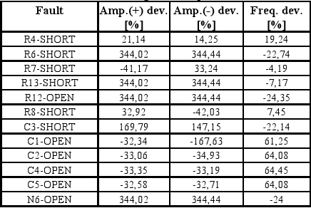
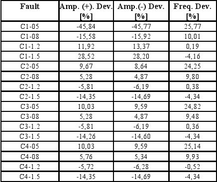
Table 8. Deviation-fault simulation results.
Four-integrator shaper.

Table 9. Deviation-fault simulation results.
Four-integrator shaper (cont).

It is important to remark that the proposed OBT scheme presents catastrophic-fault coverage of 100% implementing only amplitude measurements. This becomes an important issue if the test engineer is interested only in the detection of this kind of faults because it is possible to formulate a test scheme with a low test-time and with a low circuit overhead. By other way, optimal deviation-fault coverage is not possible although simultaneous amplitude and frequency measurements were implemented. Despite this fact, the results are very promising and similar to the previously reported by other authors.
VIII. CONCLUSIONS
In this paper is addressed the problem of testing continuous-time nuclear pulse shapers, providing a complete and efficient test solution using OBT. Three and four integrator shapers configurations are targeted. The OBT scheme proposed here is different from the previously reported by other authors. In those papers, the filters are partitioned for testing purposes, giving a test scheme with a relatively important intrusion in the original system and incrementing the time required for the test, which has to be performed in successive test
sessions. In this work, the system is not partitioned in low-order sections with the aim of maintain a low level of intrusion in the original circuit. For implementing the OBT oscillators, only the input and the main output are manipulated. In this way the complexity of the test controller and the test time are both minimized. Additionally, the performance degradation due to the addition of the test circuitry is also reduced. This is a very important issue for the test of instrumentation systems like the addressed in this paper.
For determining the oscillation conditions is adopted a graphical-analytical technique based on the frequency response plots obtained from the SPICE simulator. The DFA is used for modeling the non-linear elements present in the oscillators. Using the proposed methodology, the limit-cycle conditions are successfully determined. Despite this fact, the errors in the oscillation parameters are low only when Mode1 is forced.
In order to validate the proposed OBT schemes are adopted the widely accepted catastrophic and deviation fault models for the passive components. For the addressed faults, the fault simulation results show that the proposed OBT schemes allow obtaining high fault coverage, similar to the previously reported by other authors. Additionally, the circuitry required for implementing the test is simple and presents a low overhead. All these issues make the approach very appealing for testing the addressed shapers.
IX. REFERENCES
1. Arabi, K. and B. Kaminska, "Oscillation-test strategy for analog and mixed-signal integrated circuits", Proc. 14th VLSI Test Symposium, Princeton, United States, 476-482 (1996). [ Links ]
2. Arabi, K. and B. Kaminska, "Oscillation-test methodology for low-cost testing of active analog filters", IEEE Trans. on Instrumentation and Measurement, 48, 798-806 (1999). [ Links ]
3. Gibson, J., Non-linear Automatic Control, McGraw-Hill, Japan, 431-436 (1963). [ Links ]
4. Huertas, G., D. Vázquez, A. Rueda and J. Huertas, "Effective oscillation-based test for application to a DTMF filter bank", Proc. Int. Test Conference, Atlantic City, United States, 549-555 (1999). [ Links ]
5. Huertas, G., D. Vázquez, A. Rueda and J. Huertas, "Testing mixed-signal cores", Proc.13th Brazilian Symposium on Integrated Circuit Design, Manaus, Brazil, 307-312 (2000). [ Links ]
6. Huertas, G., D. Vázquez, E. Peralías, A. Rueda and J. Huertas, "Practical oscillation-based test in analog filters: experimental results", Proc. Int. Workshop on Electronic Design, Test, and Applications, Christchurch, New Zealand, 18-24 (2002a). [ Links ]
7. Huertas, G., D. Vázquez, E. Peralías, A. Rueda and J. Huertas, "Oscillation-based test in over sampled sigma-delta modulators", Microelectronics J., 33, 799-806 (2002b). [ Links ]
8. Huertas, G., D. Vázquez, E. Peralías, A. Rueda and J. Huertas, "Oscillation-based test in bandpass over sampled A/D converters", Microelectronics J., 33, 927-936 (2003). [ Links ]
9. Huertas, G., Test Basado en Oscilaciones de Circuitos de Señal Mixta, Tesis de Doctorado, Universidad de Sevilla, Sevilla, España (2004). [ Links ]
10. Kac, U. and F. Novak, "All-pass SC biquad reconfiguration scheme for oscillation-based analog BIST", Proc. 9th IEEE European Test Symposium, Corsica, France, 133-138 (2004). [ Links ]
11. Knoll, G., Radiation Detection and Measurement, Third Edition, John Wiley & Sons, United States (2000). [ Links ]
12. Pavan, S. and Y. Tsividis, "An analytical solution for a class of oscillators, and its application to filter tuning", IEEE Trans. on Circuits and Systems-I: Fundamental Theory and Applications, 45, 547-556 (1998). [ Links ]
13. Peretti, G., E. Romero, G. Huertas, D. Vázquez and J. Huertas, "Oscillation-based test in high order ladder filters", Proc. VI IEEE Latin American Test Workshop, Salvador, Brazil, 277-282 (2005). [ Links ]
14. Roh, J. and J. Abraham, "A compressive signature analysis scheme for oscillation test", IEEE Trans. on Computer-Aided Design of Integrated Circuits and Systems, 22, 1409-1423 (2003). [ Links ]
15. Romero, E., G. Peretti and C. Marqués, "Oscillation test strategy: a case study", J. of Electronic Testing: Theory and Applications, 20, 389-396 (2004). [ Links ]
16. Romero, E., G. Peretti, G. Huertas and D. Vázquez, "Test of switched-capacitor ladder filters using OBT", Microelectronics J., 36, 1073-1079 (2005). [ Links ]
17. Santo, M., F. Novak and S. Macek, "Design of oscillation based test structures for active RC filters", IEE Proc.-Circuits Devices Syst., 147, 297-302 (2000). [ Links ]
18. Wong, M., "On the issues of oscillation test methodology", IEEE Trans. on Instrumentation and Measurement, 49, 240-245 (2000). [ Links ]
Received: April 21, 2006.
Accepted: November 9, 2006.
Recommended by Subject Editor Julio Braslavsky.

