


Serviços Personalizados
Journal

Artigo
 Inglês (pdf)
 Artigo em XML
 Referências do artigo
 Enviar este artigo por email
Indicadores
-
 Citado por SciELO
Links relacionados
-
 Similares em
SciELO
Similares em
SciELO
Compartilhar

 Permalink
Latin American applied research
versão impressa ISSN 0327-0793
Lat. Am. appl. res. v.37 n.3 Bahía Blanca jul. 2007
A practical strategy for controlling flow oscillations in surge tanks
G. C. Nunes1, A. A. Rodrigues Coelho2, R. Rodrigues Sumar2 and R. I. Goytia Mejía2
1 Research Center of PETROBRAS - CENPES 22411.001 - Rio de Janeiro - RJ - Brazil
E-mail: giovani@cenpes.petrobras.com.br
2 Department of Automation and Systems, Federal University of Santa Catarina Box 476 - 88040.900 - Florianópolis - SC - Brazil
E-mail: {aarc,sumar,rodrigog}@das.ufsc.br
Abstract — The use of accumulation vessels -production separators, electrostatic treaters, etc- as filters of feed oscillations has been proposed to optimize the offshore treatment of crude oils. This change in philosophy of control suggests letting the level to oscillate within certain limits -called band- for which existing algorithms require the measurement of the flow rate. An alternative algorithm is presented in this paper that requires only the measurement of the level. The basic concepts of the proposal are presented. It is demonstrated that besides being simpler, this algorithm has a good performance when compared to the traditional PI controller for surge tanks conception in surge tanks.
Keywords — Level Control. Load Regulation. Outflow. Stabilization. PI Controllers. Surge Tank.
I. INTRODUCTION
First of a series of separation equipment in petroleum production plants, gravity separators are used for two and three phase separation of gas, oil and water. It feeds dedicated treatment systems designed to specify each of these streams for exportation. In offshore units the inflow of separators is oscillatory, frequently characterized by slugs of liquid and gas coming from the wells, a flow regime generically named slug flow (Shinskey, 1996; Skogestad, 2003). Proportional and Integral, PI, controllers are used for level and pressure control. Precise load regulation is adopted to avoid upsets such as liquid carry over, gas carry under, etc. As the integral mode guarantees offset free response for the controlled variables - level and pressure - flow perturbations are not filtered and oscillations are passed to the downstream treatment systems. In general oscillations are minor and this is no cause of concern (Luyben, 1990).
However, flow conditions in platforms, offshore Brazil, are becoming more stringent and higher amplitude slugs have achieved frequencies that result in significant degradation of performance of such plants. Furthermore, in a move to reduce dimensions of offshore platforms, very compact equipment are increasingly more used for water and oil treatment. Their reduced volume makes them especially sensitive to oscillations (Nunes, 2004; Junior, 1997).
Thus, an algorithm that is able to dampen the oscillatory feed of gravity separators is desirable. The aim is to keep the manipulated flow as constant as possible, while maintaining the level (or pressure) within bounds. A variety of such proposals is found in the literature: non-linear control, feedforward, proportional control, etc, which are presented under many different names: surge control, level averaging control, etc. However, from an operational point of view most of these applications have serious drawbacks: some require extra measurements (i.e., flow rate), others are hard to tune, and some allow excessive volume change (Cheung and Luyben, 1979; McDonald and McAvoy, 1986).
With that in mind, an algorithm named Band control has been developed by Petrobras. Its conception is simple and no extra measurement is required beyond that of the controlled variable. The concept applies to any accumulating vessel.
II. TRADITIONAL PI LEVEL CONTROL
Consider the material balance of liquids in separators. For a vessel with length C and diameter D with equivalent dimensions, and assuming a linear relationship between the height h and the volume, in which case volume is V=Ah=CDh, then
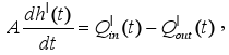 | (1) |
where  is the inflow volumetric flow rate,
  is the outflow volumetric flow rate and the character "|" represents the deviation around the nominal operating point. The piping and instrumentation diagram (P&ID) of a gravity surge tank separator is shown in Fig. 1.
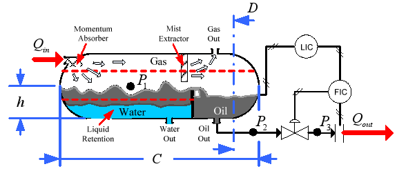
Figure 1. P&ID of a gravity surge tank separator.
The output flow is not significantly induced by the liquid level since the pressure P1 is higher than the liquid pressure, which means P2=P1+ρgh ≈ P1. For simplicity the openness dynamic of the control valve is considered fast, that is,
 | (2) |
where Cv is the flow coefficient, f(x) is the valve characteristic, x is the percentage of the valve openness, ΔP is the pressure drop in the valve, γ is the relative density and u is the control action.
Consider further that the dynamics of the valve is much faster when compared to the other components of the system. It means that the control action, u, is similar to the opening of the valve. The material balance becomes
 | (3) |
whose Laplace transform is given by
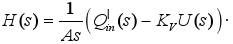 | (4) |
In process industry the PI controller provides good loop properties and normally is used in level and average level control. PI transfer function is (Åström et al., 1994)
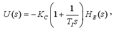 | (5) |
where HE(s) corresponds to the level error, KC e TI are parameters of the PI. The block diagram and the PI control structure of a gravity surge tank separator are given in Fig. 2.
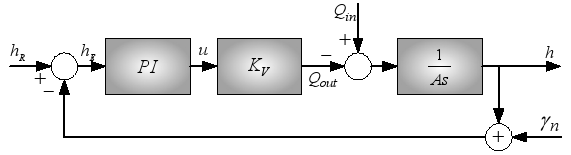
Figure 2. PI control of a gravity surge tank separator.
III. LEVEL CONTROL WITH LOAD ESTIMATION
One of the many possible ways to use gravity separators for the dampening of inflow, an industrial application that uses the measurement of outflow to infer the inflow, will be analyzed. Consider the level control of a separator as in Fig. (2). If the controlled variable is kept as close as possible to the setpoint then an increase of inflow results in a similar increase in outflow. Thus, no filtering is done. Conversely if the level is allowed to oscillate then the outflow is more constant. However, there are maximum and minimum limits allowed to the level, which depend on many factors, such as the chemical nature of the crude, type of downstream equipment, etc. For the condition when the level is out of bounds the algorithm has to aggressively bring it back to the interior of the band. Some algorithms use variable proportional action, some use gain scheduling, other switched to a fast PI (Shinskey, 1996). We will focus the analysis on the control within the band. To promote the filtering capacity desired, the outflow should be the average inflow while the level is allowed to oscillate inside these limits, or band. For that an estimate of the inflow is necessary, which can, theoretically, be inferred from the material balance of the vessel. The drawbacks to this approach will be discussed hereon.
A. Conventional Controller Design
According to Eq. (1) the dampening of the inflow of vessels without restrictions on the level has a trivial solution:  and "^" represents the estimated value.
Alternative schemes found in the literature to estimate the magnitude of inlet flowrate  are:
are:
i. Set as 20% of the typical outlet flowrate,
. 20% step change is a fairly large flow disturbance, and thus the resulting control settings will not often trigger an alarm (Friedman, 1994).
ii. Use a random-walk noise discrete model as considered by Kelly (1998) and Horton et al. (2003).
iii. Implement a new level control loop configuration, based on the vessel identification, as proposed by Wu et al. (2001).
In this paper the outflow is considered the time average of the inflow. Using Eq. (1) the inflow can be estimated from the measurements of the outflow and the derivative of the level such as,
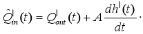 | (6) |
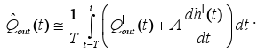
The time average of the inflow,  , should be calculated along the period T of the disturbance, where T can be tuned with the arrest time (Tarrest - time to reverse direction after a disturbance), from
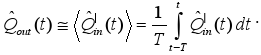 | (7) |
So, the control law is
 | (8) |
This equation indicates that the control signal can be estimated using the measurements of  and h'(t). Its implementation can be done using an outflow controller, FIC, whose setpoint is the calculated value of Qout(t), a cascade control. However, the use of this equation should be avoided first because calculating derivatives amplifies errors and as a consequence filters become necessary. Furthermore, obtaining the time average of derivatives is a waste of efforts as it results in the difference between the actual and past values of the level, a much simpler numerical procedure. Still, other drawbacks can be shown to this control law. To further investigate this apply Laplace to Eq. (8) to get
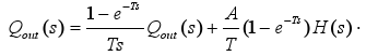 | (9) |
Based on the material balance the transfer functions are obtained as follows:
 | (10) |
and
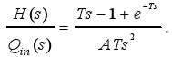 | (11) |
The frequency analysis shows that dampening of sinusoidal waves is done correctly; i.e., Qout(t) is constant, as long as T corresponds to the exact period of the wave. However, no clear period can be defined for slug flow. As a consequence, after the passage of a slug, the final value of the level may be located anywhere inside the separator (e.g., very close to the limits of the band) which is undesired. This behavior is a direct consequence of the term (1 - e-Ts)H(s).
As no restrictions were imposed during the development of the mathematical problem to allow for the regulation of the level this algorithm has rigorously speaking only one tuning parameter T, related to the frequency of the inflow. From a practical point of view it lacks a tuning mechanism able to change the strength of the filter. To get around this disadvantage a proportional and integral controller, LC, is necessary (Kothare et al., 2000).
The block diagram of such implementation is seen in Fig. 3. Note that the LC will compete with the term (1-e-Ts)H(s) and tuning is a difficult task. Finally, this implementation has 5 tuning parameters: 2 for the LC, 2 for the FIC and T, as shown in Fig. (3).
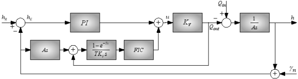
Figure 3. Level control with smoothness of the outflow.
B. Band Controller Design
A simpler and more robust controller can be derived from the same initial control law, Eq. (9). Consider the equation of the valve Qout(s) = KVU (s), which relates its opening to the outflow. Substituting it in Eq. (10) we get a control law that is independent of flow measurements. Furthermore, we suggest substituting the second term (whose origin comes from an attempt to correctly predict the inflow by adding to the outflow the contribution of volume change) by a proportional controller which is, from a practical point of view, another way to correct the differences between Qout and Qin.
The control law becomes
 | (12) |
or
 | (13) |
where HE(s) = HR(s) - H(s), λ is a fine tuning parameter and

This way K is the tuning parameter lacking. A higher value of K makes this controller a stronger regulator. The offset caused by a proportional control is irrelevant first because it is small and also because we are dealing with a system subject to a variable feed for which no steady state is foreseen. The block diagram of this controller is shown in Fig. 4.

Figure 4. Band control with smoothness of the outflow.
For the specific application of level control it has been named Level Band Control. The closed-loop transfer functions are
 | (14) |
and
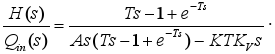 | (15) |
Note that K allows the change of poles of the system. Although this controller has only two tuning parameters, T and K, its project is more consistent with the original purpose of filtering slug flow in gravity separators.
C. Comparative Block Diagrams
An intuitive way to compare algorithms is through the use of block diagrams. The block diagram of Fig. 3 can be recast into the one seen in Fig. 5. Rearranging once again we get Fig. 6.
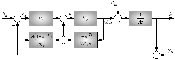
Figure 5. Level with manipulation of the Fig. (3).

Figure 6. Level with manipulation of the Fig. (5).
Remembering that as has been shown, the average value of the derivatives is the difference in values of the level, and after cancellation of common terms we then get Fig. 6.
Compare it to the block diagram of the Band control, Fig. 4 to see that the use of the FIC and the calculation of the average value of the derivatives is unnecessary.
D. Analogy with PI Controller
First order Padé approximation
 | (16) |
can be used to derive a controller under the mask of a PI structure. Substituting Eq. (16) in Eq. (13) the transfer function of the Band control is reduced for
 | (17) |
So, a proportional and integral controller is obtained as shown in Fig. 7. In this case the integral time TI is set as T/2. This approximation gives good results and simplifies significantly the implementation. Bear in mind that the integral term should not be limited (reset wind-up) and the horizon of the integral should correspond to the period T.

Figure 7. Analogy of the Band and PI control structures.
E. Adaptive Band Controller Design
The idea to adapt the gain on control in surge tanks is not new. Haugen (2004) uses a least square method, first, to identify a transfer function model, and next, to calculate the controller parameters based on performance rates. This adaptive Band control approach does not use any adaptability for the plant and the controller gain is changing each time the level limits are broken.
The Band control is switched to a fast PI every time the level is outside the limits of the band. In order to avoid using the PI and to make Band strategy more robust, an adaptive conception is proposed. The parameter T of the Eq. (7) is adjusted as 4Tarrest. The new adaptive term K is the self-tuning gain of the Band controller, Eq. (13), that is adapted according some criterion determined when the level is out of limits. Two adaptive conceptions are implemented as follows (Ljung, 1999):
Adaptive Gain with Exponential Variation: In this conception the gain K is switched for a high value and varying exponentially according one of the following discrete-time criterions:
 | (18) |
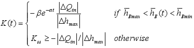 | (19) |
where α, β > 1,  ,
,  are tuned by the operator. ΔQin is the magnitude of the flowrate change, Δhmax is the allowable level change and
  is the moving average value of the system error.
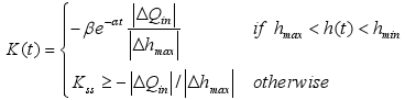
Adaptive Gain with Error Bounded: This conception is derived from the covariance resetting technique, where the gain K leads for a directly proportional value of error, when the absolute error becomes out the maximum value
 | (20) |
For the field tests all adaptive strategies and Band control were implemented in the discrete-time approach with sampling period based on the surge tank bandwidth.
IV. RESULTS AND DISCUSSIONS
A case study was done on a gravity separator described in Table 1 (platform P-07 in Campos Basin, offshore Brazil).
Table 1 Parameters for the surge tank, platform P-07.

Simulations were done in Matlab to evaluate the performance of the Band control under the same (field) conditions and parameters are shown in Table 2.
Table 2 Parameters for level controllers.

Data were recorded for period of 12 hours with a sampling time of 6 seconds. Inflow values, Fig. 8, were measured from the plant.
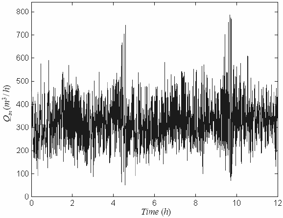
Figure 8. Inflow behavior of the plant.
Figure 9 presents responses of the plant with the PI controller tuned by operational personnel. Level values show load changes occurring at a period of 2:20 hours. However, outflow values show that higher frequency disturbances are not filtered appropriately.

Figure 9. Level, outflow and error responses for the PI controller.
Figures 10 and 11 show the comparison between the existing PI and the level Band control. A smaller time period was used, from 5:00 to 6:00 hours. It can be observed that the level fluctuates and the corresponding stabilization of the outflow is achieved using the level Band control.

Figure 10. Level response for Band and PI controllers.
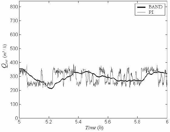
Figure 11. Outflow response for Band and PI controllers.
Results show that outflow filtering is very good. During most of the time the level is kept within the limits of the band. Note that the limit of the band (between 1.6 and 1 meters) corresponds to a volume of 12.8 m3. Another band could have been used instead, as long as it corresponds to the same volume.
Next, Fig. 12 shows the results for the Band control in nonadaptive and adaptive forms. Parameters of the adaptive level Band control, for the Eqs. (18)-(20), are α = 1, β = 2, = 1.6, = 1 and Kss = -0.48. The following proposals were analyzed.
- BAL is the Band controller with adaptive gain exponential variation based on level bounded Eq. (18);
- BAME is the Band controller with adaptive gain exponential variation based on mean error bounded, Eq. (19);
- BACR is the Band controller with variable gain based on covariance resetting, Eq. (20).
In addition, time domain indices (IAE is the integral of the absolute error, HEmax is the maximum value of the error output, σ(h) is the output variance, and σ(Qout) is the outflow variance) achieved for Band control algorithms are shown in Table 3.

Figure 12. Level, outflow and error responses for nonadaptive and adaptive Band controllers.
In addition, time domain indices (IAE is the integral of the absolute error, HEmax is the maximum value of the error output, σ(h) is the output variance, and σ(Qout) is the outflow variance) achieved for Band control algorithms are shown in Table 3.
It can be observed from Table 3 that the BAME approach reduced IAE, HEmax, σ(y) values of 31%, 47% and 55%, respectively. But, looking at oscillations in the outflow, the best behavior is given by BACR technique. Thus, these adaptive Band controllers can pave a good solution for load regulation in liquid level control.
Table 3 Indices of the Band controllers.

It can be observed from Table 3 that the BAME approach reduced IAE, HEmax, σ(y) values of 31%, 47% and 55%, respectively. But, looking at oscillations in the outflow, the best behavior is given by BACR technique. Thus, these adaptive Band controllers can pave a good solution for load regulation in liquid level control.
Responses indicate that little effect on the level and outflow behavior is obtained. So, from the viewpoint of operators and implementation costs, the adaptive Band control is a good alternative design for controlling the level variable.
A. Benefits of the Band Control
The following benefits are attributes to the Band control implementation:
- Simple and easy to implement;
- Does not require the measurement of flow;
- Applicable to all accumulation vessels;
- Applicable to the water, oil and gas phases;
- Promotes stabilization of outflow of separators that improves the performance of all downstream equipment;
- Stabilizes the flow and pressure in the exportation pipeline.
V. CONCLUSIONS
The use of the material balance for the development of controllers that stabilize the outflow of accumulation vessels has been analyzed. It is shown that the use of derivatives of the controlled variable should be avoided.
A new and simple control algorithm based on the material balance has been presented. It is shown that regardless of its simplicity its performance is superior to similar algorithms. An alternative form is presented for implementation as PI. Field data was used to simulate its use in a gravity separator of a platform. Results show enhanced performance compared to the PI currently used.
Finally, three adaptive level Band controllers were assessed with spotlight for BAME and BACR conceptions in accumulating vessels.
ACKNOWLEDGEMENT
The authors gratefully acknowledge the support of the PETROBRAS/CENPES and UFSC.
REFERENCES
1. Åström, K.J.; C.C. Hang and B.C. Lim, "A new Smith predictor for controlling a process with an integrator and long dead time", IEEE Trans. on Automatic Control, 39, 343-345 (1994). [ Links ]
2. Cheung, T.-F. and W.L. Luyben, "Liquid-level control in single tanks and cascades of tanks with proportional-only and proportional-integral feedback controllers", Ind. Eng. Chem. Fundam., 18, 15-21 (1979). [ Links ]
3. Friedman, Y.Z., "Tuning of averaging level controller", Hydrocarbon Processing Journal, 73, 101-104 (1994). [ Links ]
4. Haugen, F., PID Control of Dynamic Systems, Tapir Academic Press, 1st edition (2004). [ Links ]
5. Horton, E.C., M.W. Foley and K.E. Kwok,. "Performance assessment of level controllers", International Journal of Adaptive Control and Signal Processing, 17, 663-684 (2003). [ Links ]
6. Junior, O.A.P., "Measurement and comparative results in the petroleum production unit Pargo (in Portuguese)", Internal Report, CENPES/ DIPLOT/ SEPROT (1997). [ Links ]
7. Kelly, J.D., "Tuning digital PI controllers for minimal variance in manipulated input moves applied to imbalanced systems with delay", The Canadian of Chemical Engineering, 76, 967-975 (1998). [ Links ]
8. Kothare, M.V.; B. Mettler; M. Morari; P. Bendotti and C.M. Falinower, "Level control in the steam generator of a nuclear power plant", IEEE Trans. Cont. Syst. Technol., 8, 55-69 (2000). [ Links ]
9. Ljung, L., System Identification: Theory for the Users. Prentice-Hall, Upper Saddle River, New Jersey, 2nd edition (1999). [ Links ]
10. Luyben, W.L., Process Modeling, Simulation and Control for Chemical Engineers. McGraw-Hill Inc., New York, 2nd edition (1990). [ Links ]
11. McDonald, K.A. and T.J. McAvoy, "Optimal averaging level control", AIChE Journal, 32, 75-86 (1986). [ Links ]
12. Nunes, G.C., "Band controller for primary processing: applications and basic concepts (in Portuguese)", Internal Report, CENPES/PDP/TE-022 (2004). [ Links ]
13. Shinskey, F.G., Process Control Systems: Application, Design and Tuning. McGraw-Hill Inc., New York, 4th edition (1996). [ Links ]
14. Skogestad, S., "Lower limit on controller gain for acceptable disturbance rejection", International Symposium of Advanced Control of Chemical Processes (ADCHEM-2003), Hong Kong (2003). [ Links ]
15. Wu, K.L.; C.-C. Yu and Y.-C. Cheng, "A two degree of freedom level control", Journal of Process Control, 11, 311-319 (2001). [ Links ]
Received: July 14, 2006.
Accepted: January 29, 2007.
Recommended by Subject Editor Jorge Solsona.

