


Servicios Personalizados
Revista

Articulo
 Inglés (pdf)
 Articulo en XML
 Referencias del artículo
 Enviar articulo por email
Indicadores
-
 Citado por SciELO
Links relacionados
-
 Similares en
SciELO
Similares en
SciELO
Compartir

 Permalink
Latin American applied research
versión impresa ISSN 0327-0793
Lat. Am. appl. res. vol.40 no.1 Bahía Blanca ene. 2010
ARTICLES
CFD Approach using a discrete phase model for annular flow analysis
F.A.R. Pereira1, C.H. Ataíde2 and M.A.S. Barrozo3
1 ESSS - Rod. SC-401, Parque Tecnológico Alfa, Prédio Celta, sl-401, Florianópolis-SC, Brazil.
2,3Chemical Engng. Department, Universidade Federal de Uberlândia, Campus Santa Mônica,Bloco 1K, Uberlândia-MG, Brazil.
1ressel@esss.com.br, 2chataide@ufu.br, 3masbarrozo@ufu.br
Abstract - Fluid flows in annular regions are highly relevant in the oil industry. As a result of the ever more frequent need to increase production capacity, increasingly greater flows are applied in oil wells. However, this has led to load losses along the annular borehole/shaft, which represent a significant portion of the total energy to be supplied. Hence, the determination of these losses plays an important role in the design of these units. Using Computational Fluid Dynamics (CFD), this work investigates the field of viscoplastic fluid flows in annular spaces based on analysis of the profiles of pressure drop, entrance length, axial and tangential velocities, and on the flow path prediction. These variables are usually considered relevant for an understanding of well drilling mudflow and the particles transported by it. The predictive ability of the technique utilized here was confirmed by its congruence with the experimental pressure drop data and with the literature.
Keywords - CFD; Helicoidal; Anullar Flow; Discrete Fase Model; Non-Newtonian; Flow Path.
I. INTRODUCTION
Since the early 1980s, the oil industry has focused increasing attention on the flow of fluids in annular spaces, both in drilling, with the cuttings transport by drilling mud, and in the artificial lifting of oil by progressing cavity pumping (PCP). Operating cost concerns and the need to increase production capacity have led to the use of ever-increasing flows, and hydrodynamic losses along the borehole/shaft annuli have come to represent a significant portion of the overall energy to be supplied, so their determination has taken on a relevant role in the design of these units (Dake, 2001).
Technological advances have placed horizontal drilling in the forefront of this field since the 90s. Despite its high implementation costs, this system allows for the exploitation of thin reservoirs and also vertical fractures, expanding the horizons of oil prospecting. The exploitation rate is another extremely favorable aspect, since it is usually 3 to 5-fold higher than that of vertical wells. The operational safety and physical integrity of the well are also features of the horizontal drilling arrangement (Franchi, 2001).
One of the proposals that stand out in the literature is that of Nouri et al. (1993), who experimentally evaluated the annular flow of Newtonian and non-Newtonian fluids in situations above the laminar flow, using the laser anemometry technique to quantify the axial, radial and tangential velocity profiles. Their experimental determinations, however, did not predict the effect of internal axis rotation.
Similarly, Escudier and Gouldson (1995) also experimentally studied Newtonian and pseudoplastic flows under the influence of the shaft rotation. Using the LDA (laser Doppler anemometer) as the measuring technique, these authors presented velocity profiles for a variety of flow situations (fluid flow and rotation of the internal cylinder) and highlighted the friction factor under the influence of the flow.
Based on the results of an experimental unit of Mobil E&P, McCann et al. (1995) determined the influence of the flow on the pressure drop along an annuli with rotation of the internal cylinder, and found the drop in pressure behaved differently depending on the flow regime. Under an eccentric turbulent regime, the drop in pressure in the annular region increased as the rotation of the internal cylinder raised, while, under laminar flow, the drop in pressure decreased as the rotation increased. The authors presented similar results for the concentric design.
Escudier et al. (2002) evaluated the effect of internal cylinder rotation on the laminar flow of non-Newtonian fluids in an eccentric annular region, checking their numerical simulations of two-dimensional flow against experimental data. Their comparison of simulated velocity profiles and those obtained experimentally showed a good agreement. These authors also analyzed the effect of the attrition factor under the influence of the flow condition and the eccentricity of the arrangement.
In terms of viscoplastic fluid flow, Hemphill and Ravi (2005) studied concentric laminar flow under the influence of internal axis rotation. These authors pointed out the absence of congruence among some results reported in the literature and proposed a real scale experimental study, together with numerical techniques, to predict the velocity profiles in the annular space. Their results pointed to an increment in the pressure drop under influence of shaft rotation at speed exceeding 100 rpm, although in some cases, their numerical simulations indicated a reduction of the pressure gradient.
The main objective of this study is the use of CFD tool in order to provide a better comprehension about the annular non-Newtonian flow under influence of shaft rotation. The results show relevant differences in the flow pattern for eccentric layouts. The core flow is more considerable than the expected helical flow, usually observed in concentric scenarios. This different behavior in the flowfield is very important to drilling operations especially in cuttings transport applications.
II. GOVERNING EQUATIONS
Founded on the classical conservation equations, the continuity equation and the components of the momentum equation are written starting from a balance in a stationary control volume through which the fluid flows. Considering the system of cylindrical coordinates, the continuity can be expressed by Eq. (l):
 | (1) |
Analogously, Eq. (2) presents, as an example, the axial component of the momentum equation:
 | (2) |
In cases of non-Newtonian fluids, dynamic viscosity shifts to effective viscosity, which is determined based on a model of rheological representation and an expression for the characteristic shear rate. In general, the effective viscosity is a function of the three invariants of the shear rate tensor. For the simulations, the classical approach of considering only the effect of the second invariant was applied, as defined by Eq. (3):
 | (3) |
III. GRID SET-UP
As a preprocessing step, the system's boundaries, its subdivisions, the types of interface and the contour faces were defined. Gambit version 2.0.4, a commercial software to build and to mesh models for CFD calculations, was used to set up the virtual unit.
We began by defining the plan of dimensions for the grid set-up. The three-dimensional plan was chosen because it allows one to study the flow evolution and was a differential point of view from the research works reported in the literature, most of which use the two-dimensional domain.
The main focus of this study - the annular region - is composed of two cylindrical bodies: an external body with a 67 mm diameter and an internal one with a 32 mm diameter, both with a length of 1500 mm.
In analysis of the position of the internal cylinder in relation to the external one, two configurations were defined: concentric (e=0.0) and eccentric (e=0.75) arrangements.
In the grid construction, at the beginning of the subdivision into cells, the annular section was divided into four quadrants in order to achieve a better condition of orthogonality. This strategy was adopted due to the absence of symmetry in the eccentric design, and was also applied to the concentric arrangement so as to maintain the same procedure in both cases. Once the four quadrants were defined, we proceeded to the division, using the strategy of division by intervals rather than by fixed dimensions. Although the two strategies are quite similar, the strategy of dividing by intervals shows a greater capacity to divide sections of distinct dimensions with the same number of grids. Figure 1 shows the division of the circular section into 60 intervals, with 15 subdivisions in the concentric and eccentric annular space, a configuration that provides 900 cells per face.

Figure 1: Annular grid design.
The division structure created for the annular section was extended to the peripheries of the external and internal pipes. The external pipe divisions were the same as those of the internal pipe in order to maintain a proportionality factor.
After concluding the grids division of the "faces" of the system, the grid was enclosed in a single volume employing hexahedral cells with the mapping strategy, making a total of 92.700 cells for both concentric and eccentric cases. To conclude the preprocessing phase, the "boundary faces" were defined, i.e., the faces corresponding to the entrance, exit, walls and interior of the system.
IV. SIMULATION PARAMETERS
The procedure for the numerical simulation was implemented using the commercial CFD software, Fluent version 6.2.16.
The following conditions were defined in the simulations of this study: three-dimensional stationary regime, laminar flow, and segregated resolution strategy.
The PRESTO! routine was adopted for the pressure interpolation schemes, and the SIMPLEC algorithm was used for the velocity and pressure coupling. As a strategy of discretization of the momentum equation the QUICK routine was used due to its performance in hexahedral grids.
With regard to the convergence criteria for the residuals of the continuity equation and the momentum equation components, the value of 0.0001 was adopted for all the parameters.
A particularity for high rotation situations is that the simulation process was implemented in stages. In this strategy, one begins the numerical simulations starting from a flow condition without rotation of the internal axis. Once one has obtained the convergence results of the simulation (analysis of residuals), one continues increasing the rotation gradually. The result thus obtained will serve as the initial condition for the next increment of rotation. In this way, the simulation process can be optimized with the least computational effort, resulting in a reduction of simulation time.
V. FLOW CONDITIONS
The simulated flow conditions were referenced in the experimental tests from Ataíde et al. (1999), following an experimental plan of central composite-type experiments with three replications at the central point. Table 1 summarizes the simulation conditions employed here using the two design types: concentric and eccentric.
Table 1. Simulated flow conditions.

VI. PHYSICAL PROPERTIES OF THE FLUIDS
The information concerning the fluid's non-Newtonian rheology was determined based on Herschel-Bulkley's rheological model, according to Eq. (4), with the data for the xanthan gum suspensions quantified using a Brookfield model RDV-III viscosimeter, as presented by Ataíde et al. (1999).
In cases of non-Newtonian fluids, dynamic viscosity shifts to effective viscosity (Eq. 4), which is determined based on a model of rheological representation and an expression for the characteristic shear rate.
 | (4) |
Using the viscosity equation to adjust them to four parameters, the rheological curves revealed coefficients of quadratic correlation higher than 0.99. Table 2 lists the values of the parameters of Herschel-Bulkley's model obtained by nonlinear regression.
Table 2. Rheological parameters of the HerschelBulkley model

The concentrations of polymer were sufficiently low (less than 0.55%) to preclude any significant variation in the suspension's density value.
VII. RESULTS OF THE PRESSURE DROP AND VELOCITY SIMULATIONS
This section presents the principal flow field results of viscoplastic fluids in concentric and eccentric annuli. The flow path can be determined based on this information, using the discrete phase model.
The numerical simulation in three dimensions enabled us to observe the entrance length (EL) effect on the annular flow. This effect is the distance required for the fluid to reach the situation of fully established flow.
The simulations results indicated that the EL effect was more marked in the eccentric case, and was more sensitive to the influence of the fluid's viscosity and flow rate. The conditions implemented here showed that the length adopted (1500 mm) was sufficed to allow for the fully established flow condition.
The knowledge of this effect is an important parameter for estimating the size of pilot and experimental units according to the flow regimes to be investigated.
Also based on numerical simulation, we were able to determine the values of static pressure at the wall of the external pipe along its entire length. The pressure drop values were obtained taking as reference value the static pressure at the entrance to the annuli. The polymeric concentration and the flow rate showed a marked effect on the pressure drop.
Figure 2 illustrates tests 15, 16 and 17, highlighting the effects of the xanthan gum concentration at a constant flow of 1.2 m3/h and a constant rotation of 300 rpm in the concentric case. Similarly, tests 11, 12 and 17 depicted in Fig. 3 reveal the influence of the flow on the hydrodynamic losses at an unvarying polymeric concentration (0.40%) and rotation (300 rpm), also for the concentric case.
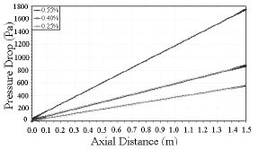
Figure 2 - Pressure drop in tests 15, 16 and 17.

Figure 3 - Pressure drop in tests 11, 12 and 17.
The effects of rotation predicted by the numerical simulation were congruent with the tendency shown by the experimental determinations reported by Ataíde et al. (1999). Figure 4 presents a typical result of the reduction in pressure influenced by the rotation of the internal axis, found in tests 10, 13 and 14 for the concentric case, at a constant flow of 1.2 m3/h and polymeric concentration of 0.40%.

Figure 4 - Pressure drop in tests 10, 13 and 14.
The pressure drop reduction caused by the shear rate increase, is related to the flow regime. In the present work the rotational effect has a local influence, local enough to not disturb the layers of the laminar flow, close to the shaft a local effective viscosity reduction is induced at the pseudo plastic fluid. This local viscosity drop reduces the friction close to the shaft wall, actuating as a lubricant. This local drag reduction justifies the pressure drop decrease. In other scenarios if the rotation is continuously raised until break the "laminar layers", the induced turbulence will cause a sudden increase at the overall pressure drop; as observed at Hemphill and Ravi (2006).
The effect of the relative position of the internal axis in relation to the external pipe was quantified by comparing the results of the two experimental designs. In all the simulated cases, the eccentricity had a reducing effect on the pressure drop in the annuli. A comparison of the 34 tests analyzed for the concentric (e=0.00) and eccentric (e=0.75) cases showed an average reduction of 21.4% in the pressure drop.
In quantitative terms, the 34 pressure drop results obtained by numerical simulation were congruent with the experimental data, pointing to average deviations of 3.3% for the concentric cases and of 3.2% for the eccentric ones.
According to some authors, the flow field can also be analyzed from the Cartesian profiles of the velocity components. This type of presentation allows one to make simultaneous comparisons of the magnitude of the axial and tangential components.
Because the simulations were carried out in a three-dimensional environment, the original 1320 mm section was adopted as reference. In this position, we also elected the axis of the abscissas, in the dimension of the external pipe diameter (radial distance), to plan the results.
Initially, we can highlight the flow rate effects on the velocity profiles. Tests 11 (0.2 m3/h) and 12 (2.2 m3/h) for the concentric case, at constant 0.40% and 300 rpm, are depicted, respectively, in Fig. 5 and 6.

Figure 5 - Velocity profiles for test 11 (e=0.00).

Figure 6 - Velocity profiles for test 12 (e=0.00).
As a guidance reference, the red lines indicate the boundaries of the external pipe wall, while the gray region (in the center) represents the presence of the internal cylinder (shaft).
Note the presence of the resultant value of the velocity components, hereinafter called magnitude velocity. This type of profile helps to elucidate the contribution of each component, revealing its possible predominance in the flow through the annular space.
Note the presence of symmetry between the two planes of the annuli, indicating physical coherence in the simulations implemented here. Another point to highlight in Fig. 5 is the predominance of tangential flow in relation to axial flow. As can be seen, the magnitude profile is practically superimposed over the tangential velocity profile.
Unlike the condition of test 11, the condition of test 12 (Fig. 6) shows not only a higher order of magnitude of the velocity values, but also a predominantly axial flow through the annular section. However, it is important to emphasize the contribution of the tangential flow, particularly in the region closest to the shaft.
Figure 7 illustrates the rotation influence, based on test 14 (600 rpm) in the concentric arrangement. Again, note that the conditions of concentration at 0.40% and flow at 1.2 m3/h remain unaltered.

Figure 7 - Velocity profiles for test 14 (e=0.00).
These results demonstrate the combined effects of high flow and rotation through the annuli, in which the contribution is both axial and tangential, without predominance in the flow.
Altering the configuration of the two pipes leads to a significant modification in the flow profile. Figure 8 shows test 14 (1.2 m3/h, 0.40%, 600 rpm), now for the eccentric case.
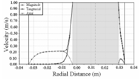
Figure 8 - Velocity profiles for test 14 (e=0.75).
In the eccentric case, in addition to the difference between the orders of magnitude of the axial velocity profiles, the annulus also shows a distinct profile. The region with the largest annular space shows a predominantly axial flow while the region with the smallest annular space displays a mostly tangential flow. Still with regard to the effects of tangential velocity, note the effect only in the regions closest to the internal cylinder. As can be seen, its contribution is almost nil in the largest annular space which extends from the central part of this region to the wall of the external pipe.
VIII. DISCRETE PHASE MODEL
Discrete Phase Models can be applied to systems in which the volumetric fraction of the discrete phase is small (systems diluted with ad < 12%). The trajectory of the particles (understood as bubbles, droplets, small solid structures, etc.) can be associated to the flow effects considering the instantaneous or average fluctuations of the continuous phase velocity. Independently of the consideration adopted, the particles do not exert any influence on the generation or dissipation in the continuous phase (Lagrangian approach). The Discrete Phase Model in a stationary state is indicated for cases in which the particles are injected into a continuous phase and the system itself has well-defined entrances and exits.
The resource used to outstand this effect was the Lagrange approach for particle tracking (one-way coupling), were the continuous phase flowfield solution is used to predict the path of particles (this strategy considers that the particle does not affect the results of momentum equations for the fluid flow).
The particles path is predicted through the integration of the momentum equation, which involves a balance between the principal forces acting upon the discrete phase, as described by Eq. (5) for an axial direction.
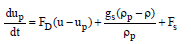 | (5) |
The term 'FD (u - up)' represents the drag forces per unit mass of the particle's terminal velocity and can be represented by Eq. (6).
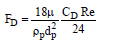 | (6) |
In the above equations, 'u' represents the velocity of the fluid phase, 'up' is the velocity of the particle, '?' is the fluid's density, '?p' is the particle's density, and 'dp' is the particle's characteristic diameter.
The assumption of fluid particle aims to represent a small part of fluid - a particle with the same fluid density (to avoid settling due to gravitational effects), to guarantee that this specific particle will create/draw the fluid flow line for visualization purposes.
The drag coefficient, 'CD', can be calculated using models available in the literature. The term 'Fx', in the other hand, represents all other additional forces per unit mass that may act upon the particle path. As an example, there is the virtual mass force, which represents the force required to accelerate the fluid in the neighborhood of the particle, and is a relevant factor when the fluid's density exceeds that of the particle.
In version 6.2.16 of the commercial software Fluent, the correlations available for predicting the drag coefficient were initially developed for Newtonian fluids. However, using the concept of effective viscosity together with the experimental data of terminal drop velocity of particles in non-Newtonian fluids described in the works of Pereira (1999) and Melo (2003), we were able to evaluate the congruence between the experimental determinations and the proposal of Haider and Levenspiel (1989), represented by Eq. (7):
 | (7) |
The parameter 'f' represents the particle shape factor while 'Re' is the dimensionless number of Reynolds, applied to the definition for the generalized Reynolds number 'ReG'.
The experimental ranges of particle size and density and also the fluid rheology allowed us to ascertain the validity of the expression within a wide range of flows. The 28 experimental points and the respective values predicted by Eq. (7) showed an average deviation of 6.5%, which was considered satisfactory considering the high nonlinearity of its behavior, within a wide range of applications (0.1<ReG<1000).
Once the equation for drag prediction, using discrete phase modeling (Lagrangian approach) has been defined, one can evaluate the path of a "particle" of fluid (same density as the fluid) flowing in the annular space along the axial length of the pipe.
IX. SIMULATION OF THE FLOW PATH
This part of the study consisted of a qualitative evaluation of the flow behavior through the annular space, aimed at confirming the helicoidal flow. Using discrete phase modeling and the results of the flow field obtained numerically and detailed earlier herein, we identified the trajectory of a "particle of fluid" flowing along the annulus.
Among the cases evaluated, in the concentric case, two points stand out particularly, i.e., the independence of the starting point of the "particle" of fluid in the annular region as a function of the symmetry plan and the influence of the rotation of the internal axis.
Figures 9 to 11 represent typical results for the concentric case, respectively, for tests 13, 17 and 14 of the experimental design (Table 1).
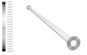
Figure 9 - Trajectory for test 13.

Figure 10 - Trajectory for test 17.

Figure 11 - Trajectory for test 14.
The face shown in blue corresponds to the entrance of the annuli (starting point for the "particle" of fluid) and the face in red represents the exit region. In order to facilitate the observation of the figures, the representation of the external pipe was excluded, keeping only the internal cylinder as reference.
Figure 9 shows a straight trajectory for test 13, due to the absence of rotation of the internal cylinder, independently of the position of entry into the annular space.
In Fig. 10, note that the cylinder rotation at 300 rpm (test 17) promotes two complete turns of the "particle" of fluid around the axis, characterizing the helicoidal flow. Although the trajectory may change according to the starting point, the behavior characterized by the number of turns is maintained.
Figure 11 indicates that the increment in rotation to 600 rpm altered the "particle" of fluid path, increasing the number of revolutions around the internal cylinder .
The remaining conditions tested here showed that same behavior, i.e., helicoidal trajectories of the fluid, with the number of turns around the axis being a function of internal axis rotation and flow rate.
In order to compare the two configurations, the strategy employed for the cases with eccentric design was the same as that used in the concentric condition. It was found that the entry position of the "particle" of fluid in the eccentric case affects the trajectory described due to the absence of a symmetry plan.
The lack of rotation, similarly to the concentric arrangement, allows for the development of a straight trajectory in any part of the annular space, as indicated in Fig. 12.

Figure 12 - Trajectory for test 13.
In the eccentric case, the effects of rotation were less marked in the development of the helicoidal flow. Figure 13 depicts the effect of a rotation of 300 rpm on the flow of a "particle" of fluid under the conditions of test 17.

Figure 13 - Trajectory for test 17.
Note, in Fig. 3, that, for the eccentric case in the starting condition in the lower region of the annuli, the shaft rotational captures the "particle" of fluid, but the latter soon follows its flow path in the larger annular section. As can be seen in this configuration, the classical configuration of helicoidal flow was also absent.
With an increment of the internal axis rotation to 600 rpm (test 14), the core flow behavior is also visible. Figures 14 and 15 highlight the effects of rotation in the two entry conditions in the annuli.

Figure 14 - Trajectory for test 14.

Figure 15 - Trajectory for test 14.
Note, in Figs. 14 and 15, that the effect of increasing the rotation of the internal cylinder was to eliminate the helicoidal flow, independently of the starting position of the "particle" of fluid.
In the starting condition in the region of the smaller annular space, there is a predominance of tangential flow, which is not sufficient to characterize a trajectory around the internal pipe. The path developed by the "particle" of fluid again followed the core flow regime.
This indicates that the combination of high eccentricity and high axis rotation can eliminate helicoidal flow; in these cases the flow is predominantly the core flow type.
IX. CONCLUSIONS
The numerical simulations of pressure drop were in agreement with the experimental results, both qualitatively (in terms of tendencies) and quantitatively (with average deviations of less than 4%).
The velocity profiles obtained here allowed for a better understanding of the flow conditions, enabling one to identify preferentially axial, tangential or mixed flows. These evaluations help shed further light on the flow field, expanding the application of velocity profiles to the entrainment of suspended particles through the annular space.
The use of discrete phase simulation enabled us to visualize the helicoidal flow and ascertain the significant influence of the rotation of the internal axis. In the case of flows in highly eccentric arrangements, the predominant type of flow was found to be core flow.
Presenting this formulation the authors elucidate the potential for further investigation about particle transport (gravel particles) in order to simulate the wellbore cleaning; considering that specific drag correlations should be necessary, as shown in Eq. (7) for particles motion in non-Newtonian flow.
REFERENCES
1. Ataíde, C.H., F.A.R. Pereira and M.A.S. "Barrozo, Wall effects on the terminal velocity of spherical particles in Newtonian and non-Newtonian fluids", Brazilian Journal of Chemical Engineering, 16, 387-394 (1999). [ Links ]
2. Dake,L.P., Fundamentals of Reservoir Engineering Developments in Petroleum Science, Elsevier Science, Amsterdam (2001). [ Links ]
3. Escudier, M.P. and I.W. Gouldson, "Concentric annular flow with center body rotation of a Newtonian and a shear-thinning liquid", International Journal of Heat and Fluid Flow, 16, 156-152 (1995). [ Links ]
4. Escudier, M.P., P.J. Oliveira and F.T.Pinho, "Fully developed laminar flow of purely viscous non-Newtonian liquids though annuli, including effects of eccentricity and inner-cylinder rotation", International Journal of Heat and Fluid Flow, 23, 52-73 (2002). [ Links ]
5. Franchi, J.R., Principles of Applied Reservoir Simulation, Gulf Professional Publishing, USA (2001). [ Links ]
6. Haider, A. and O. Levenspiel, "Drag coefficient and terminal velocity of spherical and non spherical particles", Powder Technology, 58, 63-70 (1989). [ Links ]
7. Hemphill, T. and K. Ravi, "Calculation of drillpipe rotation effects on fluids in axial flow: an engineering approach", SPE Annual Technical Conference, Dallas, Texas, October (2005). [ Links ]
8. Hemphill, T. and K. Ravi, "Pipe Rotation and Hole Cleaning in an Eccentric Annulus", IADC/SPE Drilling Conference, SPE 99150 (2006). [ Links ]
9. McCann, R.C., M.S. Quigley, M. Zamora and K.S. Slater, "Effects of high-speed pipe rotation on pressures in narrow annuli", SPE Drilling and Completion, 96-103 (1995). [ Links ]
10. Melo, F.R.G, "Utilização de câmera de alta velocidade no estudo da dinâmica de esferas em líquidos", Dissertação de Mestrado, Faculdade de Engenharia Química, Universidade Federal de Uberlândia, Brasil (2003). [ Links ]
11. Nouri, J.M., H. Umur and J.H. Whitelaw, "Flow of Newtonian and non-Newtonian fluids in concentric and eccentric annuli", Journal of Fluid Mechanics, 253, 617-641 (1993). [ Links ]
12. Pereira, F.A.R., "Estudo do movimento de partículas em fluidos pseudoplásticos: coeficiente de arraste e efeito de parede", Dissertação de Mestrado, Faculdade de Engenharia Química, Universidade Federal de Uberlândia, Brasil (1999). [ Links ]
Received: April 25, 2008.
Accepted: February 15, 2009.
Recommended by Subject Editor Walter Ambrosini.

