


Servicios Personalizados
Revista

Articulo
 Inglés (pdf)
 Articulo en XML
 Referencias del artículo
 Enviar articulo por email
Indicadores
-
 Citado por SciELO
Links relacionados
-
 Similares en
SciELO
Similares en
SciELO
Compartir

 Permalink
Latin American applied research
versión impresa ISSN 0327-0793
Lat. Am. appl. res. vol.42 no.3 Bahía Blanca jul. 2012
A Comparison of slurry and inmobilized TiO2 in the photocatalytic degradation of phenol
F.V. Silva†, M.A. Lansarin† and C.C. MORO‡
† Chemical Engineering Department, Federal University of Rio Grande do Sul (UFRGS) R. Eng. Luis Englert, s/n. CEP: 90040-040 - Porto Alegre - RS - BRAZIL, marla@enq.ufrgs.br
‡ Solids and Surfaces Laboratory. Institute of Chemistry, Federal University of Rio Grande do Sul (UFRGS) - Postal Box 15003; CEP 91501-970 - Porto Alegre - RS - BRAZIL, celso@iq.ufrgs.br
Abstract— The photocatalytic degradation of phenol was studied using slurry and immobilized TiO2 as catalysts in order to compare the specific reaction rate constants, ks and kp. Losses from phenol evaporation, the time necessary to reach adsorption equilibrium, irradiation effects and photolysis rates were quantified. ks was determined under rate-optimizing operating conditions, and kp was determined using the amount of immobilized catalyst mass that gave the maximum pollutant degradation rates. ks was two times larger than kp when the calculations were made on catalyst mass basis. Experiments performed to study catalyst deactivation showed that kp was approximately one-half of its initial value after 18 hours of phenol photodegradation. Also, among the photocatalytic degradation reactions of rhodamine B, tetracycline and phenol, the ratio of ks to kp was between 2.1 and 5.3 when the calculations were made on catalyst mass basis.
Keywords— Phenol; Rhodamine B; Tetracycline; Photocatalysis; TiO2
INTRODUCTION
Many studies of the photodegredation of phenol catalyzed by TiO2 illuminated with UV and near-UV light have been reported, and the phenol degradation pathways in the UV/TiO2 system are well documented (de Lasa et al., 2005; Gorska et al., 2009). The data in Table 1 indicate pseudo-first order kinetics for phenol photodegradation in slurry reactors. Even in studies employing identical catalysts and initial phenol concentrations, the reported pseudo-first order specific reaction rate constants differ significantly, limiting the usefulness of the data.
The studies presented in Table 1 were conducted in slurry reactors. When slurry reactors are operated as photocatalytic reactors, the catalysts must be kept separate from the degraded products; this requirement leads to significant additional costs in reactor operation. However, the use of immobilized catalysts in photocatalytic reactors can simplify their operation and reduce their operational costs.
Table 1: Literature values of phenol photocatalytic degradation using batch slurry reactors with TiO2.
Several studies have compared the decomposition of substrates using suspended and immobilized catalysts (Li et al., 2010; Grieken et al., 2009; Scotti et al., 2009; Ochuma et al., 2007a; Cho et al., 2005; Ling et al., 2004; Mehrotra et al., 2005; Dijkstra et al., 2001). However, these studies reached different conclusions. Slurry systems were variously reported to be more efficient, less efficient, and as efficient as the immobilized systems.
To assist in the scaling-up of photocatalytic reactors, this study aims to establish the differences between the effects of suspended and immobilized catalysts on the decomposition of a substrate.
Preliminary experiments were carried out to confirm that the disappearance of phenol was only caused by photocatalytic degradation. To test this, phenol losses by evaporation, the time to reach the adsorption equilibrium, irradiation effects and photolysis rates were measured. The optimum catalyst loading conditions for the adopted configuration were then identified, and the reaction rate of the slurry batch reactor was determined. Measurements of the slurry catalyst were compared to those of the immobilized catalyst. Catalytic activity losses were also studied.
II. METHODS
All measurements presented in this work were repeated three times, and the averages of the observations are reported.
A. Materials and reactants
Experiments were carried out in a 1 L glass cylindrical reactor, which was jacketed, covered with aluminum foil and enclosed in a wooden box with a built-in fan.
The radiation source was a 125 W high-pressure mercury vapor lamp (Philips, 7.02 W m-2 at 365 nm) with a modified bulb that allowed pass-through of wavelengths greater than 350 nm. The lamp was positioned at a distance of 0.16 m above the liquid surface. TiO2 (Degussa P-25, 80% anatase and 20% rutile, 50 m2 g-1) was used without prior treatment.
Phenol solutions (Vetec), NH4OH (Synth), Na2H PO4.7H2O/NaH2PO4.7H2O (Synth), 4-aminoantipyrine (Sigma) and K3[Fe(CN)6] (Merck) were prepared with distilled and deionized water. All reactants were P.A. grade.
B. Phenol degradation in a slurry reactor
To achieve phenol adsorption equilibrium at the catalyst surface, the reactor was maintained without irradiation for 45 minutes after being loaded. Three milliliter samples were collected every 30 minutes with a syringe-catheter system. The samples were then centrifuged, diluted (1:10) and analyzed. The maximum reactor volume variation was 30 mL, which was considered negligible. The initial pHs of the solutions used in all experiments were measured to be 6.5.
To determine the time required to reach phenol adsorption equilibrium at the catalyst surface, experiments were carried out in the slurry reactor with bubbling air, 300 mg L-1 TiO2 and 50 mg L-1 phenol and without irradiation.
To quantify the effects of evaporation, experiments were conducted in the absence of catalyst and radiation. Photolysis effects were evaluated by irradiating the reactor without the catalyst. Both experiments were conducted with bubbling air.
To determine the role of UV irradiation, a mercury lamp (Philips) and three black-light bulb lamps (Ecolume, Taschibra and Foxlux) were each used as radiation sources in the same apparatus. The peak emissions of these lamps were all measured at 365 nm with a Cole Parmer 9811-50 radiometer.
To determine the optimum catalyst loading parameters, experiments were conducted in the previously described experimental apparatus, using four different catalyst concentrations: 200, 300, 400 and 500 mg L-1.
The initial concentration of phenol was 50 mg L-1 in all experiments.
C. Support preparation and catalyst immobilization
TiO2 (P-25, Degussa) was immobilized onto glass plates (4.5 cm x 4.5 cm x 3 mm). The plates were blasted with glass particles to roughen their surfaces, and then treated with a 4 M NaOH solution for 24 hours. After rinsing with water, the plates were treated with a 2 M HCl solution for two hours, rinsed with distilled water and dried in an oven.
The suspension method was used to immobilize the catalyst onto the plate surface. A suspension of 2 g of TiO2 in 100 mL of distilled and deionized water was prepared. This suspension was continuously agitated with a magnetic stirrer for 30 minutes to promote complete homogenization. The pretreated plates were placed into a container with a rough upper surface; then, tNext, the catalyst suspension was poured onto the plates, and the system was incubated for 30 minutes. The plates were removed from the suspension, dried at 100 °C for 20 minutes, and then, calcinated at 450°C for 30 minutes. The same methodology was repeated two additional times, yielding plates having three immobilized layers. Catalyst deposited onto the sides and bottom of the plate was removed, and the plates were weighed to determine the amount of TiO2 deposited onto their surfaces.
The surface structure of the prepared catalyst film was examined using a scanning electron microscope (Jeol JSM 5800) operated at 10 kV and 50 μA. The plates' surface areas were evaluated by measuring the adsorption of methylene blue.
The stability of deposited film catalyst was evaluated by a 20h test, during which the plate with the immobilized catalyst was removed, dried in an oven and weighed every 2 hours. In this test the immobilized catalyst was placed at the reactor bottom in the horizontal position, and bubbling air was used for agitation. The plate was covered with 1 cm of pure water, and the plates were prepared with 0.10 ± 0.01g of catalyst.
D. Experiments using immobilized catalyst
The experiments were carried out like described in Part C, but using phenol solution instead of water, at an initial concentration of 50 mg L-1. A 125 W mercury lamp (7.02 W m-2 at 365 nm) was used to irradiate the reactor. The reactor was placed into a wooden box cooled with a fan. For the deactivation studies, the samples were collected every 30 minutes over 3 hours, centrifuged and analyzed. The initial pH of the solutions used in all experiments was measured to be 6.5.
In all experiments presented in this work, the phenol concentration was measured using a colorimetric method based on the 4-aminoantipyrine reaction (APHA, 1998) that determines the total phenol content.
III.RESULTS AND DISCUSSIONS
A. Phenol degradation in a slurry reactor
i) Determination of evaporative losses
No significant phenol losses were observed in the 90-minute experiments, even in those with bubbled air flow. The results presented in Fig. 1 are the averages of three experiments (2.4% relative error). For comparison, a phenol degradation curve is also shown.
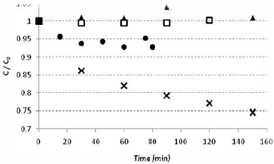
Figure 1: Preliminary experiments showing phenol losses through three pathways: (•) adsorption, (  ) evaporation, (
 ) photolysis and (x) phenol degradation (Cph = 50 mg L-1, V = 1 L, I0 = 7.02 W m-2 and Qair= 13 mL s-1).
ii) Phenol adsorption at the catalyst surface
In order to exclude non-equilibrium effects from the photodecomposition rate measurements, the adsoprtion equilibration time was measured. The adsorption experiments showed a 5% variation in the phenol concentration (Fig. 1). Therefore, before all other experiments, the solution and catalyst were mixed without irradiation for 45 minutes to establish equilibrium. The equilibrium concentration was considered the initial concentration for the degradation reactions.
iii) The direct photolysis effect
Photocatalysis requires both irradiation and TiO2. In the absence of the catalyst, there was no significant reduction in the phenol concentration after approximately 120 minutes of irradiation (Fig. 1). Phenol has two absorption peaks (210 and 270 nm), both in the UV-C spectrum and outside of the emission spectra of the lamps used eliminating the possibility of direct degradation (Philips, Technical Catalogue).
iv) Phenol photocatalytic degradation kinetics
In the present study, the model described by de Lasa et al. (2005) was adopted. This model is based on the Langmuir-Hinshelwood model, presented in Eq. 1, where rph is the rate of phenol disappearance in mg L-1 min-1; kph-o-DHB, kph-p-DHB, kph-1,2,4-THB, kph-1,4-BQ, kph-CO2 are the phenol specific reaction rates to ortho-dihydroxybenzene, para-dihydroxybenzene, 1,2,4 trihydroxybenzene, 1,4 benzoquinone and CO2, respectively, in min-1; Cph is the phenol concentration in mg L-1; Kj is the adsorption constant in L mg-1; Cj is the concentration for each of the species present in the reaction in mg L-1; and t is the time in minutes.
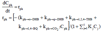 | (1) |
The colorimetric method was used to determine the total amounts of phenol and ortho- and meta-substituted phenols. The mechanism described by de Lasa et al. (2005) does not include formation of the meta-substituted compound. In this mechanism, formation of ortho-substituted compound is inhibited at pH 7 (similar to the pH used in the experiments described here). In the preliminary adsorption experiments in the present work (Fig. 1), phenol showed low adsorption to the catalyst surface. Because the phenol concentration is low, the KphCph term in the denominator can be neglected, which reduces Eq. 1 to Eq. 2.
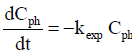 | (2) |
Therefore, the experiments studying the phenol degradation were compared using kexp as the response variable: ksexp for the slurry reactor and kpexp for the immobilized catalyst.
v) The catalyst loading effect
A catalyst concentration of 300 mg L-1 was found to maximize the specific reaction rates (ksexp=0.0013 min-1) (Fig. 2). Up to this maximum, higher catalyst concentrations increased the number of irradiated particles until all particles were illuminated. Higher catalyst concentrations increased the system's opacity and decreased the process efficiency (Gogate and Pandit, 2004).

Concentration TiO2 (mgL-1)
Figure 2: Effects of catalyst concentration (V = 1 L, C0 = 50 mg L-1, T = 30 °C, pH 6.5, Qair = 13 mL s-1 and I0 = 7.02 W m-2).
vi) Irradiation effects.
To test the effects of irradiation, the incident radiation in the reactor was varied while all other conditions were held constant. The observed reaction rate had a nonlinear dependence on the irradiation (I) (Fig. 3). This behavior is similar that described in earlier reports (Herrmann, 2005; Ochuma et al., 2007b); the relationship is linear for low incidence values, becomes proportional to I0.5 as the irradiation increases and ultimately becomes constant with I. The subsequent phenol degradation experiments were performed with incident radiation of 0.7 mW cm-2.
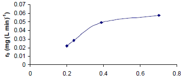
l0 (m Wcm-2)
Figure 3: Phenol photocatalytic degradation rate dependence on incident irradiation.
The experimental reaction rate constant ksexp, obtained using the optimum phenol degradation parameters (V = 1L, Cph = 50 mg L-1, T = 30 °C, Ccat = 300 mg L-1, pH 6.5 and I = 7.02 W m-2), was 0.0013 min-1 with an R2 = 0.9922. This correlation indicates that the phenol photocatalytic degradation follows the expected pseudo-first order kinetics.
B. Phenol degradation using immobilized catalyst.
Figures 4a and 4b show the plate micrographs obtained by scanning electron microscopy. The surface was relatively uniform but contained cracks and pores ranging from approximately 0.2 to 0.7 µm in size. The immobilized catalyst surface area was determined to be 8.2 m2 g-1 using methylene blue adsorption.

Figure 4: Plates micrographs: (a) 40X and (b) 2000X.
The stability of deposited film catalyst test showed that the catalyst mass loss after 20h was less than 1%, which enabling carried out long duration tests.
The suspended catalyst measurements were used in the immobilized catalyst experiments. It was assumed that phenol losses resulting from evaporation and photolysis could be ignored and that the dark time must be a minimum of 45 minutes. The catalyst was tested in the optimum conditions for the slurry reactor: pH 6.5 and I = 7.02 W m-2. When the plate was used for the first time, the obtained kpexp was 0.0010 min-1.
C. Results comparison for the suspended and immobilized catalysts.
For batch reactors (de Lasa et al., 2005),
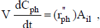 | (3) |
where Cph is the phenol concentration (g cm-3), V is the reactor volume (cm3) occupied by phenol solution,  is the rate of phenol disappearance per illuminated area (gph min-1 cm-2), Ail is the illuminated catalyst area (cm2) and
  , where
  is the specific reaction rate constant (cm min-1). We can rewrite Eq. 3 as
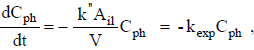 | (4) |
giving
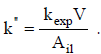 | (5) |
Similarly, considering mcat as the catalyst mass,
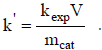 | (6) |
For both the immobilized and suspended catalysts, it is nearly impossible to determine the exact illuminated area or the corresponding illuminated mass. The aim of the present study is to achieve a practical relationship to assist in the scaling up of photocatalytic reactors. Therefore, the two approximations were used to calculate and k'.
The incident radiation (W m-2) on the catalyst was measured with a radiometer (positioned at the reactor center) and kept constant in all experiments. The constant was calculated using the illuminated area covered by the catalyst. This parameter corresponds to the area of the plate ( = 20.25 cm2) when the catalyst is immobilized and, in the slurry reactor, to the area of the transverse section (
 = 78.5 cm2).
The constant k' was calculated using the total mass of the catalyst employed in the experiment and is a parameter that can be measured with precision. For both slurry and immobilized catalysts, the experiments were performed at optimum conditions. For slurry reactors, "optimum conditions" refer to the catalyst concentration, initial pH and irradiation levels chosen to give the maximum reaction rate (Cph = 50 mg L-1, T = 30°C, Ccat = 300 mg L-1, pH= 6.5 and I = 7.02 W m-2). For the immobilized system, "optimum conditions" refer to the immobilized catalyst mass (0.10 ± 0.01g) chosen to give maximum pollutant degradation.
The observed s was 1.5 times greater than p, and the observed k's was two times larger than p.
Table 2 presents the calculated values of s, p, k's and k'p for the photocatalytic degradation reactions of rhodamine B and tetracycline obtained in previous studies in this lab and those of phenol obtained in the current study. The ratio of k's to k'p was between 2.1 and 5.3 for these pollutants.
Table 2: The calculations used for the comparison between the batch reactors with the immobilized and suspended catalysts.
Comparison of the results of this work to those found in the literature is not immediately straightforward. Working with DBU (1,8-diasabiciclo[5. 4. 0]undec-7-ene), Ochuma et al. (2007b) concluded that the immobilized catalyst was more efficient than the slurry system. However, their results were not obtained using the optimum conditions for each system, instead using identical catalyst mass concentrations. Ling et al. (2004), also working with identical catalyst mass concentrations, concluded that the two systems gave the same performance in phenol degradation. The Dijkstra et al. (2001) experiments for formic acid showed that the slurry system was four times more efficient than the immobilized one.
D. Deactivation of the immobilized catalyst
Significant catalyst deactivation was observed in the immobilized-catalyst systems. Phenol degradation generated a product that was deposited onto the immobilized catalyst surface, giving it a brown color. This deposit was not observed in the slurry reactor due to agitation. Similarly, other authors (Grzechulska and Morawski et al., 2003; Inazaki and Bidoia, 2004) found a dark deposit on the catalyst surface during phenol photocatalytic degradation.
The mechanism of this catalyst deactivation was investigated. TiO2 was immobilized onto glass plates and exposed to parallel liquid flow across the plate surface. The results are shown in Table 3. Catalyst activity decreased during irradiation, and a change in the catalyst surface color was visible after a short period.
Table 3 shows the value kpexp and k'p obtained when the standard phenol photocatalytic degradation reaction was performed several times with the same plate. After 24 hours of reaction, kpexp and k'p were 60% its initial values.
Table 3: The specific rate constants obtained when the immobilized catalyst was used repeatedly in phenol degradation.
IV. CONCLUSIONS
In this work, the TiO2-catalyzed photocatalytic degradation of phenol in a slurry reactor was studied. Phenol degradation followed pseudo-first order kinetics with a specific reaction rate of 0.0013 min-1 under conditions of 30°C, initial phenol concentration of 50 mg L-1, 300 mg L-1 of catalyst, irradiation of 7.02 W m-2 and 1 L reactor volume. The preliminary experiments showed that evaporation and photolysis were negligible as sources of phenol degradation. It was found that phenol has low adsorption onto the catalyst surface, and a dark time of 45 minutes should precede degradation experiments.
Defining K's = ksexp / Ccat and k'p = (kpexp/ mcat)V, the ratio k's / k'p was between 2.1 and 5.3 for rhodamine B, tetracycline and phenol.
Significant deactivation was observed with the immobilized catalyst. After 24 hours of reaction, kinetics constants were 60% its original values.
NOMENCLATURE
| Ail | illuminated area (cm2) |
| C | concentration (g mL-1) |
| kph-o-DHB | phenol specific reaction rates to ortho-dihydroxybenzene (min-1) |
| kph-p-DHB | phenol specific reaction rates to para-dihydroxybenzene (min-1) |
| kph-1,2,4-HB | phenol specific reaction rates to 1,2,4 trihydroxybenzene (min-1) |
| kph-1,4-BQ | phenol specific reaction rates to benzoquinone (min-1) |
| kph-CO2 | phenol specific reaction rates to CO2 (min-1) |
| kexp | experimental specific reaction rate (min-1). |
| specific reaction rate based on the illuminated area  |
| k' | specific reaction rate based on the catalyst mass  |
| Kj | adsorption constant (L mg-1) |
| m | mass(g) |
| rph | rate of phenol disappearance (g L-1 min-1) |
 | rate of phenol disappearance based on the illuminated area (gph min-1 cm-2) |
| r'ph | rate of phenol disappearance based on the catalyst mass (gph min-1 g-1) |
| t | time (min) |
| V | reactor volume occupied for phenol (cm3) |
| SUBSCRIPTS | |
| P | indicates immobilized catalyst |
| Ph | indicates phenol |
| S | indicates slurry reactor |
| Cat | indicates catalyst |
ACKNOWLEDGMENTS
The authors would like to acknowledge DEGUSSA for the catalyst donation and CNPq for the financial support.
REFERENCES
1 APHA, Standard Methods for the examination of water and wastewater, American Water Works Association, Washington (1998). [ Links ]
2. Azevedo, E.B., A.R. Torres, F.R.A. Neto and M. Dezotti, "TiO2-photocatalyzed degradation of phenol in saline media in an annular reactor: hydrodynam-ics, lumped kinetics, intermediates, and acute toxicity," Brazilian Journal of Chemical Engineering, 26, 75-87 (2009). [ Links ]
3. Buth. D.F., Degradação; fotocatalítica da tetraciclina em solução aquosa empregando TiO2 suportado, M. Sc. Thesis, Universidade Federal do Rio Grande do Sul, Brazil, Available in http://hdl.handle.net/10183/18992 (2009). [ Links ]
4. Cesconetto, G.N., Decomposição de fenol em efluente da indústria de papel e celulose por fotocatálise heterogênea, M. Sc. Thesis, Universidade Federal de Santa Catarina (2002). [ Links ]
5. Chiou, C.H., C.Y. Wu and R.S. Juang, "Photocatalytic degradation of phenol and m-nitrophenol using irradiated TiO2 in aqueous solutions," Separation and Purification Technology, 62, 559-564 (2008). [ Links ]
6. Chun, H., W. Yizhong, and T. Hongxiao, "Destruction of phenol aqueous solution by photocatalysis or direct photolysis," Chemosphere, 41, 1205-1211 (2000). [ Links ]
7. Cho, I.H., J.H. Park and Y.G. Kim, "Oxidative degradation and toxicity reduction of trichloroethylene (TCE) in water using TiO2/solar light: Comparative study of TiO2 slurry and immobilized systems". Journal of Environmental Science And Health Part A-Toxic/Hazardous Substances & Environmental Engineering, 40, 1033-1044 (2005). [ Links ]
8. de Lasa, H., B. Serrano and M. Salaices, Photocatalytic Reaction Engineering. Springer Science + Business (2005). [ Links ]
9. Dijkstra, M.F.J., A. Michorius, H. Buwalda and H.J. Panneman, "Comparison of the efficiency of immobilized and suspended systems in photocatalytic degradation," Catalysis Today, 66, 487-494 (2001). [ Links ]
10. Gogate, P.R. and A.B. Pandit, "A review of imperative technologies for wastewater treatment I: oxidation technologies at ambient conditions," Advances in Environmental Research, 8, 501-551 (2004). [ Links ]
11. Gorska, P., A. Zaleska and J. Hupka, "Photodegradation of phenol by UV/TiO2 and Vis/N,C-TiO2 processes: Comparative mechanistic and kinetic studies," Separation and Purification Technology, 68, 90-96 (2009). [ Links ]
12. Grieken R.V., J. Marugán, C. Sordo and C. Pablos, "Comparison of the photocatalytic disinfection of E. coli suspensions in slurry, wall and fixed-bed reactors," Catalysis Today, 144, 48-54 (2009). [ Links ]
13. Grzechulska, J. and A.W. Morawski, "Photocatalytic labyrinth flow reactor with immobilized P25 TiO2 bed for removal of phenol from water," Applied Catalysis B-Environmental, 46, 415-419 (2003). [ Links ]
14. Herrmann, J.M., "Heterogeneous photocatalysis: State of the art and present applications," Topics in Catalysis, 34, 49-65 (2005). [ Links ]
15. Inazaki, T.H. and E.D. Bidoia, "Tratamento fotoca-talítico de efluente simulado contendo fenol utilizando TiO2 Degussa," 17° Reunião Anual do Instituto Biológico de São Paulo (2004). [ Links ]
16. Li, D., K. Xiong, W. Li and Z.H. Yang, "Comparative Study in liquid-fase heterogeneous photocatalysis: model for photoreactor scale-up," Industrial and Engineering Chemistry Researsh, 49, 8397-8405 (2010). [ Links ]
17. Ling, C.M., A.R. Mohamed and S. Bhatia, "Performance of photocatalytic reactors using immobilized TiO2 film for the degradation of phenol and methylene blue dye present in water stream," Chemosphere, 57, 547-554 (2004). [ Links ]
18. Mehrotra, K., G.S. Yablonsky and A.K. Ray, "Macro kinetic studies for photocatalytic degradation of benzoic acid in immobilized systems," Chemosphere, 60, 1427-1436 (2005). [ Links ]
19. Ochuma, I.J., R.P. Fishwick, J. Wood and J.M. Winterbottoom, "Photocatalytic oxidation of 2,4,6-trichlorophenol in water using a cocurrent downflow contactor reactor (CDCR)," Journal of Hazardous Materials, 144, 627-633 (2007a). [ Links ]
20. Ochuma I.J., O.O. Oluwapomile, R.P. Fishwick and S. Pollington, "Three-phase photocatalysis using suspended titania and titania supported on a reticulated foam monolith for water purification," Catalysis Today, 128, 100-107 (2007). [ Links ]
21. Peiro, A.M., J.A. Ayllon, J. Peral and X. Domenech, "TiO2-photocatalyzed degradation of phenol and ortho-substituted phenolic compounds," Applied Catalysis B-Environmental, 30, 359-373 (2001). [ Links ]
22. Philips, Technical Catalogue HPLN Lamps - Mercury. Available at: http://www.luz.philips.com/archives/pt_lamps_hid_hpln.pdf. [ Links ]
23. Scotti, R., M. D'Arienzo, F. Morazzoni and I.R. Bellobono, "Immobilization of hydrothermally produced TiO2 with different phase composition for photocatalytic degradation of phenol," Applied Catalysis B: Environmental, 88, 323-330 (2009). [ Links ]
24. Silva, F.V., Aplicação da fotocatálise heterogênea para degradação de benzeno e fenol em um reator contínuo do tipo labirinto, M. Sc. Thesis, Universidade Federal do Rio Grande do Sul, Brazil, Available in http://hdl.handle.net/10183/10356 (2007). [ Links ]
25. Soares, E.T., M.A. Lansarin and C.C. Moro, "A study of process variables for the photocatalytic degradation of rhodamine B," Brazilian Journal of Chemical Engineering, 24, 29-36 (2007). [ Links ]
Received: January 25, 2011.
Accepted: October 3, 2011.
Recommended by subject editor: Orlando Alfano

