


Servicios Personalizados
Revista

Articulo
 Inglés (pdf)
 Articulo en XML
 Referencias del artículo
 Enviar articulo por email
Indicadores
-
 Citado por SciELO
Links relacionados
-
 Similares en
SciELO
Similares en
SciELO
Compartir

 Permalink
Latin American applied research
versión impresa ISSN 0327-0793versión On-line ISSN 1851-8796
Lat. Am. appl. res. vol.44 no.4 Bahía Blanca oct. 2014
Analysis of the connecting zone between consecutive sections in distillation columns covering multiple feeds, products and heat transfer stages
J.A. Reyes-Labarta†, M.D. Serrano and A. Marcilla
Chemical Engng. Department, University of Alicante, Apdo. 99, Alicante 03080, SPAIN.
† ja.reyes@ua.es
Abstract— In the present work, we provide a systematic analysis about all the streams involved in the zone connecting two consecutive sections for the design of distillation columns with different thermal feed conditions, product extractions and heat additions or withdrawals. This analysis allows a better understanding of what happens on a feed or side draw (of mass or energy) stage, what compositions are or are not in equilibrium, and the impact on internal liquid and vapor flows.
Keywords— Distillation; Side Stream; Process Design; Heat Stages; Lateral Product.
I. INTRODUCTION
Tray by tray methods for the design of distillation columns cannot compete with computer methods, but they are essential for their conceptual design. These methods do provide a clear picture of what could be expected in an approximate way along a distillation column and facilitates the visualization and best understanding of many fundamentals and important aspects of multistage distillation, such as the interrelationship of several process variables.
In this sense, typical practical calculations for the conceptual design of a distillation column, given for instance a known recovery of the key components, can be: optimal number of trays or reflux ratio, minimum number of trays (at total reflux), detecting pinched zones (minimum reflux), excessive reflux or reboil and mislocated feed streams, identifying cases where intermediate heat exchangers are attractive, etc. Therefore most mass transfer text books in chemical engineering devote some space and effort to explain tray by tray methods, such as the McCabe-Thiele method (Seader et al., 2011; Petlyuk, 2004; Stichmair and Fair, 1998; Biegler et al., 1997; Kister, 1992; King, 1980; Treybal, 1981; Henley and Seader, 1988; Benitez, 2002; Noble and Terry, 2004). However, equations for the operating lines (OL) are always developed for columns with single or multiple feed additions but product extractions and heat additions or withdrawals are not always considered.
Furthermore, the optimum point of feed introduction, which yields the least total number of trays at a particular reflux, is generally consider as the intersection point between the operative lines of the sector above and below (FP point), in order to use always at each step, the operative line that lies farther from the equilibrium curve to obtain the maximum enrichment per stage (i.e. lowest vapor composition if we start at the top of the column). Therefore, when a mass feed stream is considered, whatever its thermal condition, such optimum feed location consideration is consequent with the assumption that the feed is introduced in bulk to a single feeding tray (stage number 2 in Fig. 1a) where it mixes with the vapor of the tray below and with the liquid of the tray above. The streams leaving this feeding stage (V2=V2' and L2=L1') are considered to be in equilibrium, as in any other theoretical stage (Fig. 1a).

Figure 1. Scheme of the streams at the zone connecting two consecutive sectors using a) the classical FP approach; b) the GFOL approach.
However, this approach can be somewhat far from the physical reality, that does not allow to exactly locate all the streams involved in the changing zone of two consecutive sectors in the McCabe-Thiele diagram, and that can introduce some significant deviations in the equilibrium compositions obtained for the different trays of the column below each particular feed, especially in systems of high relative volatility and when the feed is a subcooled liquid, a partly vaporized mixture or a superheated vapor. Thus, it is more likely to consider that when a feed stream is introduced in the distillation column, it flashes adiabatically and spontaneously to the feed stage pressure, generating a vapor phase (VF) that flows to the tray immediately above, and a liquid phase (LF) that flows to the tray immediately below (Fig. 1b).
Before dealing with the general case, the differences of the classical and strict approach in the case of a single feed stream are shown in Fig. 2a-b (corresponding to the schemes presented in Fig. 1a-b), with a simplified nomenclature. With the classical approach, when the step by step construction arrives to the composition y2=y2' by using the upper section operative line (UOL), the liquid composition x2 is obtained directly from the equilibrium curve. The composition of the next vapor y3 is located in the OL of the following sector, LOL. As we can see, stream L2=L1+LF presents an inconsistent behavior in the sense that its composition (x2) is located out side the interval defined by the compositions x1 and xF (Fig. 2a).

Figure 2. Changing zone in the y/x McCabe-Thiele diagram for a) the classical FP approach; b) the GFOL approach.
In an alternative approach, what is supposed to occur is that when a feed stream is introduced between two plates in the distillation column (1 and 2 in Fig. 1b), it flashes adiabatically. The vapor fraction VF will join the vapor coming from the stage below V2, whereas the feed liquid fraction LF will join the liquid coming from the plate immediately above L1 providing two streams (V2' and L1') that are not in equilibrium: V2'=V2+VF= V2+F-LF and L1'=L1+LF, since they are the sum of two different streams that are in equilibrium. Figure 1b presents the feed operative line (FOL) and all the streams involved in the changing zone correctly located: V2, V'2, L1, L'1, L2, etc.
Thus, the objective of this paper is to point out and analyze, through a fully analytical and graphical treatment, the connecting zone between consecutive sections due to different side streams (feeds, products and/or heat removals or additions) using a Generalized Feed Operating Line (GFOL) approach. In this approach, all the streams involved in the change of sector zone, as well as the corresponding operating lines, are unambiguously located in the McCabe-Thiele diagram. The work complements, in this sense, the academic literature dealing with this subject (e.g. Ledanois and Olivera-Fuentes, 1984; Wankat, 2012). This analysis tackles most of the possible cases and leaves no room for doubt in any possible interpretation, allowing (with a negligible extra effort) an appropriate comprehension and understanding of what would happen in a column used for the separation of binary mixtures, in accordance with the hypothesis considered (condition of constant molar overflow, CMO) and regarding the way of introducing or extracting the mass or heat to the column.
It should be noted that the analysis proposed does not alter the procedure of calculation of the minimum reflux ratio by checking all the possible pinch points where the operative lines of each section intersect the equilibrium curve.
Finally it is interesting to remark that the tray by tray methods still present some attractive characteristic for the more effectively and optimal design of separation units such as their robustness due to the fact that the convergence for a feasible postulated separation is almost always guaranteed, and a near optimal design is obtained at each iteration. Additionally some references can be found in the literature dealing with transformation of variables, such as composition, so that the McCabe-Thiele method becomes applicable in special cases of traditional distillation, reactive distillation, absorption, liquid-liquid extraction and multicomponent mixtures (McCabe et al., 1993; Doherty and Malone, 2001; Reyes-Labarta et al., 2012; Ravi, 2008; Lee et al., 2000; Marcilla et al., 1997; 1999; Reyes et al., 2000; Johnson and Morgan, 1985). The extension of the McCabe-Thiele method can also be used to analyze quickly, the effects and drawbacks of different configurations for internal heat integration in a single distillation column (HIDiC), to obtain more suitable chemical processes (Nakaiwa et al., 2003; Shenvi et al., 2011; Huang et al., 2006; Ho et al., 2010).
II. SYSTEMATIC ANALYSIS OF THE CHANGES OF SECTION IN THE McCABE-THIELE METHOD
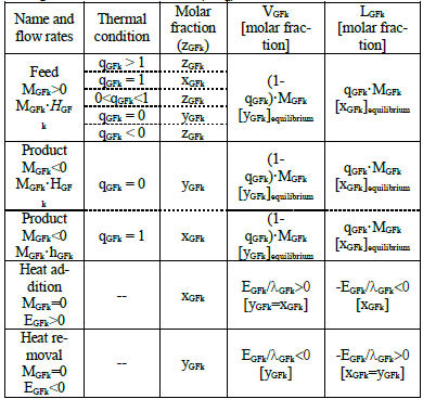
A column section can be defined as the portion of a distillation column that is not interrupted by entering or exiting streams or heat flows (Hohmann et al., 1980). Thus, two consecutive sections k and k+1 of a distillation column are separated by a generalized feed side stream, GFk. Such a generalized feed stream can be either a mass stream (MGFk) or an enthalpy stream (EGFk). Considering all these possibilities, the generalized in or out feed side stream considered and their characteristics and sign are shown in Table 1.
Table 1. Compilation of the different cases presented for a generalized feed stream (GFk) and its characteristics.
Figures 3-5 present a systematic analysis of the different possible situations, where all the streams involved are coherently located in the y/x diagram (according to their x and y characteristic compositions and nomenclature shown). In order to simplify the following figures, only compositions have been maintained in diagrams.

Figure 3. McCabe-Thiele y/x diagrams (including a schematic representations of the internal existing streams at the zone connecting consecutive sections) for a generalized mass feed stream (MGFk>0) for different thermal conditions: a) 0<qGFk<1; b) qGFk<0; c) qGFk>1; d) qGFk=1; e) qGFk=0

Figure 4. McCabe-Thiele y/x diagrams for a generalized product feed stream (MGFk<0) for different thermal conditions: a) qGFk=1; b) qGFk=0
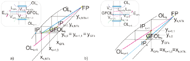
Figure 5. McCabe-Thiele y/x diagrams for a generalized heat side stream (EGFk): a) Intercondenser (EGFk<0); b) Interreboiler (EGFk>0)
Figures 3a-e represent the general situation of a mass feed stream (MGFk>0) for different thermal conditions of the feed stream. Figure 3a shows for a partly vaporized feed (0<qGFk<1), the OLs of sections k and k+1 (i.e.: OLk and OLk+1), the FLk, the GFOLk and the coherent location of all the streams involved. The vapor fraction VGFk joins the vapor coming from the stage below (Vk,0 = Vk+1,1 + VGFk), which implies that yk,0 is located between yk+1,1 and yGFk; whereas the feed liquid fraction LGFk joins the liquid coming from the plate immediately above (Lk+1,0 = L k,NTk + LGFk) which implies that xk+1,0 is located between xk,NTk and xGFk. It can be observed that the segment drawn of GFOLk covers the amplitude of an equilibrium stage in the diagram. As commented on before, this GFOLk must be used only once in the staircase construction, the first time that the condition xk,NTk ≤ xopt,k= xIPk is satisfied.
In the case of superheated vapor feed stream (qGFk< 0), FLk intercepts the equilibrium curve with a positive slope lower than unity (Fig. 3b). The vapor yGFk composition is lower than the composition of the feed (zGFk). Since VGFk>MGFk, GFOLk has a higher slope than OLk and OLk+1 and it is nearer the equilibrium line, which results unfavorable for the separation. Besides, it can be observed that yk,0 is aligned between yk+1,1 and yGFk but xk+1,0 is not located between xk,NTk and xGFk since xk+1,0 is greater than xk,NTk because this addition unfavorably affects the separation at the stage of the section change.
If MGFk is an undercooled liquid, FLk intercepts the equilibrium curve with a positive slope greater than unity (Fig. 3c). Since LGFk > MGFk, GFOLk has a slope lower than OLk and OLk+1, which is unfavorable for the separation at the specific stage of the change of section. As expected, xk+1,0 is located between xk,NTk and xGFk but yk,0 is lower than both yk+1,1 and yGFk.
In the case of qGFk=1 or qGFk=0 (Fig. 3d and e), the GFOLk coincides with the corresponding operative line k or k+1, respectively. These are the only thermal conditions for a feed stream, where the intersection point FP coincides with IPk or IPk+1 and any of the two approaches, the classical and the one proposed, gives the same results.
Obviously, for other types of side streams, different from mass feeds, it must be considered that the stream to be removed (when the GFk is a mass product: MGFk<0) or to be heated or cooled (for the case of heat addition or removal: EGFk) must actually exist in the column to avoid incoherent design predictions, and therefore zGFk (Table 1) must coincide with xk,NTk or yk+1,1 (Fig. 4 and 5).
The extraction of a product worsens the separation in the rectifying section because the slope of OLk+1 is lower than OLk, consequently more stages are needed, as compared to the case of mass feed addition. Figures 4a-b show the case of a saturated liquid or saturated vapor product. In these cases, in a similar way that for saturated feed streams, the GFOLk coincides with the corresponding operative line k or k+1. In the case of the saturated liquid product (LGFk=MGFk): zGFk=xGFk=xk,NTk= xk+1,0=xFP and yk,0=yk+1,1=yFP; while in the case of the saturated vapor product (VGFk=MGFk): zGFk=yGFk=yk,0 =yk+1,1=yFP and xk,0=xk+1,1=xFP.
Sometimes intermediate reboilers and/or intermediate condensers are used in distillation columns, normally to adjust an existing distillation column to new separation requirements or feeds. Thus for instance, a wide gap between the component balance line and the equilibrium curve in the stripping section or enriching indicates a potential for an interreboiler or an intercondenser, respectively. Obviously, the intermediate heat supply and/or heat removal causes changes of internal vapor and liquid flows (Table 1).
The intermediate heat addition or removal leads to different diagrams from mass feed and product situations. Streams VGFk and LGFk are not in equilibrium but their composition is the same (given by the same point on the diagonal: zGFk=xGFk=yGFk). Since there is neither mass addition nor removal, in the McCabe-Thiele y/x diagram of Fig. 5a-b the operative lines OLk and OLk+1 present different slopes and cut with the diagonal at the same point, giving the FP intersection point analogous to that obtained for mass feed streams. As can be observed in Fig. 5, in this case, the transition between the two consecutive operating lines shows a discontinuity.
When a heat flow EGFk is removed from a vapor of composition zGFk=yGFk=yk+1,1 causing the corresponding condensation (Fig. 5a), the flow Vk,0 entering the stage above decreases by VGFk = EGFk/λGFk, and consequently the liquid flow Lk+1,0 entering the stage below increases by LGFk = -EGFk /λGFk (EGFk<0 according to Table 1), both streams having the same composition xGFk = yGFk. The coherent construction shown in the diagram allows the fulfillment of the relationship among streams occurring at the stage of change of section: xk+1,0 is located between xk,NTk=xIPk and xGFk and yGFk = yk,0 = yk+1,1.
Because of the liquid flow increases, the slope of the GFOLk is lower than OLk but the slope of OLk+1 is higher than that of OLk. Since OLk+1 is more separated from the equilibrium line, the effect of the heat removal in the enrichment section of a column favors the separation.
An equivalent analysis can be done if heat is added to the liquid of a tray of composition xGFk causing a vaporization that implies a liquid flow decrease and the consequent vapor flow increase (VGFk=EGFk/λGFk and LGFk=-EGFk/λGF with EGFk>0 according to Table 1). The effects of these changes are represented in Fig. 5b.
Despite the presented analysis may be considered unnecessarily complex for the applications expected from the McCabe-Thiele method, we find it interesting since it does not only evidence the relationships occurring among the streams involved at the stage of the change of section, but also between them and the rest of streams at the previous or subsequent stages.
Nevertheless, differences between the two approaches are not so considerable and they depend on the thermal condition of the feed stream, the relative volatility of the system and other parameters, such as the reflux ratio, and also the position of the feed. For saturated liquid and vapor feeds both approaches give the same results, as commented previously. For the rest of cases there are two limiting situations (minimum and maximum LD/D reflux ratios) where the results obtained are also the same. For intermediate situations between minimum and maximum LD/D reflux ratios calculated differences (always lower than one tray but that can be relevant if we consider the compositions of the following trays) depend on the column characteristics and the system equilibrium. As we can see in Fig. 6a-c, the stage number tends to rise quickly in the first case (a) but for intermediate situations (b) we can see that differences are higher (especially if the last liquid descending from the previous sector lies nearly in the middle of the FOL). For the limiting case (c) both approaches tend to the same result.

Figure 6. Qualitative illustrations of the changing zone for different reflux ratios between the limiting situations: (a) LD/D near (LD/D)min; b) (LD/D)min < LD/D < (LD/D)max; c) LD/D near (LD/D)max.
Figures 7a-b show the complete staircase construction, using the feed operative line, for two numerical examples corresponding to a single column with a partially vaporized and undercooled liquid feed stream, respectively. In addition, Fig. 8a shows the comparison of the results obtained using the classical and proposed approach for the case of a superheated vapor feed. The liquid composition profile along the column is also shown (Fig. 8b). Though the number of trays obtained is very similar by the two approaches, the composition profile may significantly differ for the trays below the generalized feeds. This fact can be magnified as the number of steps or generalized feeds increase.

Figure 7. Complete McCabe-Thiele y/x diagrams for numerical examples using the generalized feed operative line (GFOL) corresponding to a single distillation column with a feed stream: a) partially vaporized; b) undercooled liquid.

Figure 8. Comparison between the classical FP approach of the McCabe-Thiele method( ) and the GFOL approach proposed (), for a single distillation column with a superheated vapor feed stream: a) staircase construction (y/x diagram); b) liquid molar fraction profile (the number in brackets indicates the percentage of relative difference between the liquid composition obtained at each tray using both approaches).
III. CONCLUSIONS
The classical approach for the McCabe-Thiele method, using the FP point, can be unrealistic and does not allow a clear understanding of the different relationships among the streams that may be involved whenever a generalized feed is introduced into a distillation column. Thus, a complete analysis (coherent with the hypothesis considered) of what may happen when changing section in a distillation column due to generalized mass or heat feed side streams, has been presented using a Generalized Feed Operating Line approach. All the streams involved in the stages corresponding to these changes of sections, as well as the operating and changeover lines are unambiguously located in the McCabe-Thiele diagram, since the understanding of the different cases is not so evident, facilitating the comprehension of the method trough its coherent and strict application. The analysis of several examples reveals that significant differences in the composition of the trays below the generalized feeds may be obtained when comparing with the traditional McCabe Thiele method.
ACKNOWLEDGMENTS
We gratefully acknowledge financial support from the Vice-Presidency of Research (University of Alicante, Spain).
SUPPLEMENTARY MATERIAL
A complementary analysis of particular cases where the compositions of the streams developed in the rectification column coincide with one of the vapor (yGFk) or liquid (xGFk) portions generated from the GFk can be found in the supplementary material. A review and extension of the McCabe Thiele method and the completed deduction of the generalized equations can also be found in the Open Academic Repository of the University of Alicante (http://hdl.handle.net/10045/23195). Additionally, a website of self-learning about the McCabe-Thiele method for the design of distillation columns can be consulted: http://iq.ua.es/McCabe-V2/ (http://hdl.handle.net/10045/2283).
LIST OF SYMBOLS
| CPL, CPV | Specific heats of liquid and vapor phase |
| D | Distillate stream (kmole/h) |
| EGFk | Effective heat flow (kcal/h) added or removed to the column, after section k, by an intermediate heat exchanger (reboiler or condenser that we consider having a 100% efficiency) to a liquid or a vapor stream, respectively |
| FLk | Feed line of feed stream k |
 | |
| FOL | Feed operating line |
| FP | Feed point: intersection point between the operative lines of the sector above and below the feed |
| GFk | Generalized feed that separates section k and k+1 (kmole/h) |
| GFOLk | Generalized feed operating line |
 | |
| HGFk | Specific enthalpy of the generalized feed mixture stream (kcal/kmole) |
| HGFk | Dew-point vapor enthalpy (kcal/kmole) |
| hGFk | Bubble point liquid enthalpy (kcal/kmole) |
| IPk | Intersection point between OLk and GFOLk |
| IPk+1 | Intersection point between OLk+1 and GFOLk |
| LD | Liquid reflux to the column (kmole/h) |
| LGFk | Liquid portion of the generalized feed stream k |
| Lk,i | Liquid from stage i of section k (kmole/h) |
| LOL | Lower section operating line |
| λGFk | Enthalpy of vaporization or latent heat (kcal/kmole) of the feed stream |
| MGFk | Mass feed or product stream that separates section k and k+1 (kmole/h) |
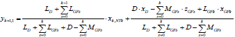
| OLk+1 | Operating line of section k+1: |
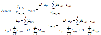 | |
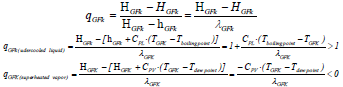
| qGFk | Thermal condition of the generalized feed stream k. Enthalpy change to bring the mass feed stream from its initial condition (HGFk) to a saturated vapor (HGFk) divided by the molar latent heat or enthalpy of vaporization of the feed lGFk (dew-point vapor enthalpy, HGFk, minus bubble point liquid enthalpy, hGFk) |
 | |
| TGFk | Temperature of the generalized feed stream k |
| UOL | Upper section operating line |
| VGFk | Vapor portion of the generalized feed stream k |
| Vk,i | Vapor from stage i of section k (kmole/h) |
| xGFk | Liquid feed composition of the volatile component (mole fraction) |
| xIPk | x coordinate of the point IPk (=xopt,k) |
| xIPk+1 | x coordinate of the point IPk+1 (=xGFk) |
| xk,i | Composition of liquid falling from stage i of section k (mole fraction) |
| xopt,kx | coordinate of the optimal location of the generalized stream k (when the staircase calculation is started from the top of the column) |
 | |
| yGFk | Vapor feed composition of the volatile component (mole fraction) |
| yk,i | Composition of vapor ascending from stage i of section k (mole fraction) |
| yIPk | y coordinate of the point IPk (=yGFk) |
| zGFk | Generalized feed composition of the volatile component (mole fraction) |
| Subscripts | |
| i | Stage |
| k | Section |
| NTk | Number of plates of the section k |
REFERENCES
1. Benitez, J., Principles and modern applications of mass transfer operations, Wiley-Interscience, New York (2002). [ Links ]
2. Biegler, L.T., I.E. Grossmann and A.W. Westerberg, Systematic Methods of Chemical Process Design, Prentice Hall, New Jersey (1997). [ Links ]
3. Doherty, M.F. and M.F. Malone, Conceptual design of distillation systems, McGraw-Hill, New York (2001). [ Links ]
4. Henley, E.J. and J.D. Seader, Equilibrium-Stage Separation Operations in Chemical Engineering, John Willey & Sons, New York (1988). [ Links ]
5. Ho, T.J., C.T. Huang, L.S. Lee and C.T. Chen, "Extended Ponchon-Savarit method for graphically analyzing and designing internally heat-integrated distillation columns", Ind. Eng. Chem. Res., 49, 350-358 (2010). [ Links ]
6. Hohmann, E.G., M.T. Sander and H. Dunford, "A new approach to the synthesis of multicomponent separation schemes", Chemical Engineering Communications, 17, 273-284 (1980). [ Links ]
7. Huang, K., K. Matsuda, K., Iwakabe, T. Takamatsu and M. Nakaiwa, "Graphical Synthesis of an Internally Heat-Integrated Distillation Column", J. Chem. Eng. Jpn., 39, 703-708 (2006). [ Links ]
8. Johnson, J.E. and D.J. Morgan, "Graphical techniques for process engineering", Chemical Engineering, 8, 72-83 (1985). [ Links ]
9. King, C.J., Chemical Engineering Series. Separation Processes, McGraw-Hill, New York (1980) [ Links ]
10. Kister, H.Z., Distillation Design, McGraw-Hill, New York (1992). [ Links ]
11. Ledanois, J.M. and C. Olivera-Fuentes, "Modified Ponchon-Savarit and McCabe-Thiele methods for distillation of Two-Phase Feeds", Ind. Eng. Chem. Process Des. Dev., 23, 1-6 (1984). [ Links ]
12. Lee, J.W., S. Hauan, K.M. Lien and A.W. Westerberg, "A graphical method for designing reactive distillation columns: I. the Ponchon-Savarit method," Proc. of the Royal Society A: Mathematical, Physical & Engineering Sciences, 456, 1953-1964 (2000). [ Links ]
13. Marcilla, A., A. Gómez and J. Reyes, "New method for designing distillation columns of multicomponent mixtures", Latin American Applied Research, 27, 51-60 (1997). [ Links ]
14. Marcilla, A., A. Gómez, J.A. Reyes and M.M. Olaya, "New method for quaternary systems liquid-liquid extraction tray to tray design", Ind. Eng. Chem. Res., 38, 3083-3095 (1999). [ Links ]
15. McCabe, W.L., J.C. Smith and P. Harriot, Unit Operations of Chemical Engineering, 5th ed., McGraw-Hill, New York (1993). [ Links ]
16. Nakaiwa, M., M.K. Huang, A. Endo, T. Ohmori, T. Akiya and T. Takamatsu, "Internally heat integrated distillation columns: A review," Chem. Eng. Res. Des., 81, 162-177 (2003). [ Links ]
17. Noble, R.D. and P.A. Terry, Principles of Chemical Separations with Environmental Applications, Cambridge University Press (2004). [ Links ]
18. Petlyuk, F.B., Distillation Theory and its Application to Optimal Design of Separations Units, Cambridge University Press (2004). [ Links ]
19. Ravi, R., "Transformations for a generalized McCabe-Thiele method: A retrospective and a new perspective," International Communications in Heat and Mass Transfer, 35, 860-866 (2008). [ Links ]
20. Reyes, J.A., A. Gómez and A. Marcilla, "Graphical concepts to orient the Minimum Reflux Ratio Calculation on Ternary Mixtures Distillation," Ind. Eng. Chem. Res., 39, 3912-3919 (2000). [ Links ]
21. Reyes-Labarta, J.A., J.A. Caballero and A. Marcilla, "A novel hybrid simulation-optimization approach for the optimal design of multicomponent distillation columns," Computer Aided Chemical Engineering, 30, 1257-1261 (2012). [ Links ]
31. Seader, J.D., E.J. Henley and D.K. Roper, Separations Process Principle. Chemical and Biochemical Operations, 3th ed., John Willey & Sons, New York (2011). [ Links ]
32. Shenvi, A.A., D.M. Herron and R. Agrawal, "Energy efficiency limitations of the conventional heat integrated distillation column (HIDiC) configuration for binary distillation," Ind. Eng. Chem. Res., 50, 119-130 (2011). [ Links ]
33. Stichmair, J.G. and J.R. Fair, Distillation: Principles and Practice, Willey-VCH, New York (1998). [ Links ]
34. Treybal, R.E., Mass Transfer Operations, Chemical Engineering Series, 3rd ed., McGraw Hill, New York (1981). [ Links ]
35. Wankat, P.C., Separation Process Engineering. Includes Mass Transfer Analysis, 3rd ed., Prentice Hall, Massachusetts (2012). [ Links ]
Received: August 18, 2013
Accepted: March 17, 2014
Recommended by Subject Editor: Orlando Alfano

