


 Inglés (pdf)
 Articulo en XML
 Referencias del artículo
 Enviar articulo por email
 Citado por SciELO
  Similares en
SciELO
Similares en
SciELO 
 Permalink
I Introduction
Microuidics is probably the most successful scientic story of recent decades 1,2. The development of the lab-on-a-chip spirit has led to a breakthrough in uid science. These developments require cleanrooms and engraving systems which are costly from both nancial and environmental points of view, which hampers the growth of the technique worldwide. Recent work has focused on low cost and reliable devices like paper micro uidics 3,4, textiles 5 and ber networks 6-8. Our aim was to perform basic micro uidic operations (mixing, routing, analysing) using the imbibition of a droplet by the ber network of the medium. The micro uidic systems were then qualied as \semi-open" systems since the liquid presents a free interface. More recently, micro uidic devices were developed based on a high hysteresis surface covered by a \neutral" liquid. The liquid of interest is directly deposited on a solid surface in the manner of a fountain pen that literally writes down the circuit 9. In the present paper a rough glass surface is considered. This low cost material has interesting wetting properties, particularly the high hysteresis of the contact line of a water droplet. Consequently, when a droplet moves along such a surface, it always releases some liquid. The wetting properties of a commercial frosted glass were studied when the plate was horizontal or inclined. In the latter case, since the droplet loses some liquid on the surface, the water droplet motion was studied in detail. In order to evaluate the in uence of this loss of liquid on the speed, the motion of the droplet was measured over a long distance, namely about 100 times the capillary length. Two liquids were considered:
silicone oil and water. The aim of the paper was to obtain a detailed description of the physical properties of frosted glass with regard to the wetting of these two liquids. This simple system is a very interesting playground for further applications. Frosted glass Rough hydrophilic surfaces are known as parahydrophilic surfaces; as summarised by Marmur 10, we can decouple the contact angle due to chemical eects (the nature of the solids, liquids and gases) from those caused by the surface texture. This kind of surface, like frosted glass, is wettable and characterised by high contact angle hysteresis (as shown in this paper). The crevices and peaks play the role of pinning centres that cause the droplet to behave in a particular way. Indeed, a water droplet sitting on frosted glass does not spread through the crevices. We can consider the droplet as being in a situation between the wicking of the surface crevices and the pinning of the peaks. On the other hand, for oil the roughness enhances wetting, as demonstrated in the seminal paper by Cazabat 11. Roughness is therefore agood way to enhance wicking between two plates 12 or hemiwicking in patterned channels of micropillars, as described in Belharz's thesis 13. The chemical nature of the surface can even increase the phenomenon of hemiwicking 14. Sliding along an inclined plane If a droplet is placed on a at surface which is then tilted at an angle , the droplet starts moving when a given angle ? is reached. The attachment force F of a droplet on a surface was investigated by Furmidge in the 60s 15-17. This force is related to the advancing contact angle a, the receding contact angle r and the surface tension of the liquid y We have

where w is the lateral width of the droplet. Consequently, on an inclined plane with a tilt angle that increases, if the driving force given by g sin ( is the density of the liquid and g is the gravity acceleration) exceeds F, the droplet with volume starts moving. The absence of hysteresis implies that the droplet can slide on any inclination. On the one hand, sliding conditions on a hydrophilic surface were detailed by Kim 18 and revisited by Le Grand 19. The droplet was found to have a teardrop shape with a singularity (the cusp) at the rear of the droplet. This cusp has been intensively discussed, 20 including the release of small droplets in the wake. For a large volume the droplet takes on the shape of a whale 21. On the whole, the motion of the droplet was shown to be more a rolling than a sliding movement 22, 23 and was modelled by several groups 24, 25. The case of a rivulet is a natural extension of droplet sliding 26; this rivulet may present meandering due to the pinning of the contact line. On the other hand, if the surface is highly hydrophobic, the droplet slides. Finding inspiration in natural surfaces like those of lotus leaves, scientists and engineers have focused on tailoring superhydrophobic surfaces: these surfaces are microtextured with pillars and coated with hydrophobic polymers 27. Anti-adhesion is also the aim of numerous studies (a good summary can be found in Ref. 28). The aim is to decrease as much as possible the contact angle hysteresis; i.e., the difference between the advancing and receding angles as predicted by the Furmidge law. The in uence of roughness was also investigated by Miwa 16 in the case of superhydrophobic surfaces. In addition, the fractal dimension of the roughness was also considered 29. They found that the higher the contact angle, the smaller the tilt angle required for the droplet to slide. Finally, the sliding conditions on a superhydrophobic surface depend on the state of the droplet: if the droplet remains on the top of the asperities (Cassie state), it may roll easily down the inclined plate; if the droplet is impaled on the asperities (Wenzel state), it will stick to the surface 27.
Furthermore, making adjustments to the contact angle enables us to obtain counter-intuitive behaviours. For example, when the inclined plate is made to vibrate, the droplet may move uphill 30,31. Some authors inserted hydrophilic patterns on a hydrophobic plane 32, 33. They managed to control the retention of liquid at precise spots. This kind of patched surface opens up the possibility of depositing particles contained in the liquid at these hydrophilic spots after evaporation. This process may lead to a coee stain eect; that is, preferential deposition along the contact line 34 which can be controlled using non spherical particles 35. This opens up novel perspectives regarding particle deposition.

Figure 1: Water droplets - (a) Pictures taken using Keyence KV-X: on the left, the frosted glass is covered by a lm of water, and on the right the frosted glass is dry. (b) Pictures taken using Filmetrics during evaporation. The surface started dewetting in the middle picture. On the right, we can see a complex network of water threads. The side dimension of the picture is about 1 mm.
Objectives Most of the literature on sliding droplets reports experiments on very controlled surfaces and a small length scale (10-20 times the capillary length). In consequence, the droplets do not release any liquid on the surface (or at least, small droplets do not 20). Droplet mass is considered to be conserved and the threshold angle for sliding and the initial speed have been discussed. We propose to study the sliding of water and oil droplets over long distances on a frosted glass plate. As the droplet moves, its weight changes due to the liquid lm released or invasion of the tortuous surface of the frosted glass.
To achieve these objectives we used a commercial frosted glass and considered two liquids: silicone oil (20 cSt) and water. The experimental details can be found in section II.

Figure 2: Water droplets { Contact angle of a 5 uL water droplet on (a) the smooth side of the glass (top) and on the rough side of the glass (bottom). (b) Water droplet sliding along the rough side of the frosted glass. This illustrates the advancing contact angle (about 80°) and the receding contact angle (0°).
First, the wetting properties on a horizontal plate were studied. The case of the water is reported in section III.i and the oil in section III.ii. Second, the motion of droplets on a tilted frosted glass plate was investigated as a function of the volumen of the droplet, and as a function of the tilt angle . The results for oil are reported in section IV.i and for water in section IV.ii. A rst approach model is detailed for the case of water in section IV.iii. In the case of water on the inclined plate, the droplet releases a thin lm that drains back into the droplet: this lm is known as the wake. The ow in the wake is discussed in section V. Finally, section VI presents some perspectives that exploit the high contact angle hysteresis of a water droplet to create microchannels and generate a micro ow. Furthermore, the micro ow inside the wake of the sliding water droplet was also investigated: we show that color pigment can be extracted from a water solution. This conclusion is reported in section VII.
II Experimental details
The frosted glass was a commercial material found under the name Satinovo Mate" (Saint-Gobain) 36. This material was chosen because it is a standard glass developed by Saint-Gobain and because the surface state is homogeneous on a large scale of the order of one meter, since the frosted surface is obtained by an acid attack.
Roughness was measured using a Bruker laser prolometer and a VK-X Keyence microscope. The arithmetic mean deviation was found to be 1.99 um for a root mean square of 2.34 um. On the sample under consideration, the maximum vertical distance between a valley and a peak was hm = 9:33 um; the peaks were separated by a distance dm of 34 10 um. Figure 1a shows two micrographs taken using the VK-X Keyence of 400 by 400 um of the frosted glass. The colors correspond to the height of the roughness: red corresponds to 17 um and blue to altitude zero. On the left, the sample was wet by water. The liquid fully covered the surface and the small asperities were wet completely. Fig. 1b shows a picture of the frosted glass taken while water was evaporating, using a Filmetrics instrument (F40-NIR with 15X objective). These pictures were taken when water started dewetting the surface in some spots, leading to this entanglement of water rivulets.
Concerning the liquids used, 20 cSt silicone oil was chosen because of its very low saturation pressure (less than 5 mmHg). This prevents any evaporation during experiments of long duration. On the other hand, working with high viscosity increases the relaxation time. For this reason the 20 cSt oil was a good compromise. The water used was bidistilled.
III Horizontal frosted glass plate
i The case of water
The contact angles of water on the smooth side and on the frosted sides were measured using a CAM200 goniometer. In this case, on the smooth side the contact angle of S = 32 5 indicates a tendency to be wet by water; the advancing and receding angles were found to be 50 and < 10 respectively. On the frosted glass side, the angle of contact was found to be F = 50 8. The advancing and receding angles were evaluated on an inclined plate and were found to be equal to 80 2 and 0, respectively. In Fig. 2a, the picture of a water droplet is shown on a piece of frosted glass (bottom) and on the same glass plate but on the smooth side (top). We can see that the roughness increases the contact angle. This is counter intuitive because the roughness is known to enhance the natural wetting tendency of the material. According to Ref. 14, the roughness of the contact angle on the frosted glass should be corrected. We can dene the roughness factor r > 1 as the ratio between the actual surface area and the apparent surface area 37. The relation between the smooth side and frosted side contact angles is given by cos R = r cos S. In the present case, factor r is about 1.14 (= 2ph2 m + (dm=2)2=dm). However, the roughness in this case plays the role of pinning centers that conne the droplet to a limited area, and consequently, the contact angle is increased. The pinning centers are so strong that the receding angle is equal to zero; indeed, the droplet releases a thin lm of liquid after its passage. The high contact angle hysteresis was clearly visible when the frosted glass plate was inclined to observe the motion of the droplet (see Fig. 2b). The front angle was close to 80, and the wake consisted of a lm of water that drained back towards the droplet. When the surface was horizontal, in the case of the rough surface the contact line remained pinned during evaporation of the droplet. Some pictures were taken during the evaporation process (Fig. 1b) using a Filmetrics device. It can be seen that dewetting occurs in dierent places of the lm (black dots in the picture in the middle and on the right). The dry spots increase in size, resulting in the entanglement of small liquid threads (picture in the middle).

Figure 3: Silicone oil spreading -(a) Superimposition of 5 pictures taken at 10, 102, 103, 104 and 105 s intervals fromabove a horizontal frosted glass plate on which a droplet (10 uL) of silicone oil was initially released. (b) Evolution of the oil stain diameter D as a function of time (log-log plot) for a droplet of 5, 7.5 and 10 uL (green diamonds, red bullets and blue bullets, respectively). The straight lines are power laws for which the exponents are indicated in the gure. The dashed line corresponds to the saturation regime for which the stain did not expand any longer. (c) Evolution of the average thickness h of the oil stain as a function of time for three droplet volumes (the same volumes and symbols are used as in (b)). Note that the data in (b) were not obtained from the pictures (a).
ii The case of silicone oil
When a droplet of silicone oil was released onto the frosted glass, the droplet spread rapidly. The position of the contact line was easy to detect because frosted glass becomes transparent when liquid covers the surface (it enters the crevices). The dynamics of the spreading was recorded by measuring the diameter of the circular oil stain on the frosted glass. In Fig. 3a successive pictures are shown between the moment of release and 10000 s (see caption). The droplet spread uniformlyin a disk of growing diameter. It is notable that the circular stain at 105 s was still easily observable thanks to the presence of a very tiny amount of oil which was suficient to make the plate transparent. As oil does not evaporate and as the oil properties are not sensitive to dust, the experiments ccould be performed over a long period. A second experiment was performed on a large plate of 580 1300 mm, also over a long period (up to three months). A simple ruler was used to measure the oil stain diameter D.
In Fig. 3b the oil stain diameter D is presented as a function of time in a log-log graph. Three dierent initial volumes of the droplet were considered:
5, 7.5 and 10 uL. The growth of the stain behaved similarly whatever the initial volume of the droplet. Several regimes can be identied in the short, medium and long term. During the first 105 s (one day) the droplet spread rapidly, then the growth rate decreased as indicated by the loglog plot of Fig. 3b. Finally, a plateau was reached after about 120 days. The contour of the stain became more dificult to see after 3 months. In the medium term, we found that D followed two power laws of time: Dt0:3 between 102 and 105 s and Dt0:15 between 105 and 107 s.
The spreading of oil on a rough surface was studied by Cazabat and Cohen Stuart 11. In this work, three regimes were identied. (i) The rst to appear, just after the positioning of the droplet, wass the capillary regime. During this regime, the radius of the stain increased following the power law Dt1=10 (this is Tanner's law 38). (ii) Afterwards, the oil invadeed the crevices, which are considered randomly distributed. This regime can be modelled as a diusion process, Dt0:5. However, because of the complexity of the crevice network, the experimental exponent belongs to the interval 0.25, 0.5. (iii) Finally, the thickness of the droplet (or the oil stain) was of the same order of magnitude as the roughness; the capillary force and the spreading speed both decreased. Applied to the present case, we observed the invasion regime between 102 and 105 s Dt0:3, then a decrease in the spreading speed Dt0:15, as also observed in Ref. 11. The plateau that we observed is new. We can assume that the oil stain stopped spreading when the plateau was reached. Considering the initial volume of oil and the surface of the oil stain, we can determine the average thickness h of the oil stain: h = 4 =(D2). In Fig. 3c we show thickness as a function of time. The average thickness h started at 10 um and gradually decreased until it reached about 100 nm. This value is obviously not realistic. The silicone oil invades the valleys of the frosted glass and probably does not cover the tops of the hills. Additional observations are required to investigate the presence of the silicone oil at microscopic level.
IV Inclined frosted glass plate
A large frosted glass plate (580 1300 mm) was placed on an aluminium frame. The angle was xed and measured using an inclinometer. Then, the droplets were released at the top of the inclined plane. Their movements were recorded using a GoPro camera which enabled us to obtain a large eld of view with suficiently high resolution (4000 3000 pixels). By thresholding the images, it was then possible to follow the motion of the droplet (in the case of water) and the position of the furthest point (tip) reached by the droplet (in the case of oil).
i The case of silicone oil
As shown in the previous section, oil literally invades the frosted glass very rapidly during the rst 10 seconds. On the other hand, on an inclined plane, gravity is responsible for movement of the center of mass of the droplet. This force increases with the angle of inclination. Consequently, the sliding of an oil droplet results in a competition between spreading and sliding. Fig. 4 shows the shape of the trace released by the droplet for ve dierent angles of inclination, for a droplet of 75 uL. The direction of sliding is towards the right of the images. The pictures shown are the result of the superimposition of pictures taken at dierent times (see caption). According to the angle (and size of the droplet), a change in morphology was observed: (i) when the center of mass of the droplet slides faster than the spreading, the stain takes on a comet-like shape, and (ii) when spreading is the dominant eect, the stain is oblong in shape. The comet shape can be observed for the angles 25, 45, 65 and 85 until the time t=500 s in Fig. 4. For a longer time period the tip of the trajectory becomes rounded. Indeed, the comet shape cannot hold for a long time because the droplet becomes lighter and lighter as some oil is released in the wake of the droplet. The loss of weight is due to spreading of the oil in a lateral direction. The oblong shape is predominant for small angles (and for small volumes), as observed in Fig. 4; = 5.

Figure 4: Silicone oil - Superimposition of several pictures of the oil stain, taken from above, for ve angles of inclination (5, 25, 45, 65, and 85, from top to bottom). In each case the volume of the droplet was 75 uL. The height of each image is 40 mm. The times at which the pictures were taken are indicated in the dierent gures and range from 0 to 4000 s. The complete set of images (taken every second) was analysed to obtain the area and the speed of the spreading presented in Fig. 5.
The sliding position of the droplet can only be evaluated by plotting the position x of the tip of the oil stain (x = 0 is the starting point), i.e. the furthest point reached by the oil stain from the starting position. In Fig. 5a, the position of the tip of the oil stain is presented as a function of time for four angles: =5, 25, 65 and 85 (see legend). The volume of the droplet was 75 uL. In Fig. 5b, the angle was kept constant (25) while the droplet volume was varied between 25 and 100 L. For each angle considered, the behaviour of the droplet was similar. First the droplet slid with a velocity that increased with the angle and the droplet mass. Afterwards, the speed decreased. Note that there was no threshold angle for the oil motion since the oil spread on the frosted glass whatever the angle. On long time scale, friction acts in addition to the lateral spreading. Moreover, the volume of the droplet at the tip decreases. These processes to be taken into account as they decrease the speed of the tip. In Fig. 5a, the position x(t) was tted by a phenomenological law

where a1, a2 and a3 are the t parameters. Note that over a long period of time (Fig. 5b) the speed tends to decrease to zero (x(t) is constant). Starting from Eq. (2), we can obtain the expression of the speed x as a function of x,

The initial speed is then given by v0 = a1a2 and we can dene a characteristic length x? = a1. This characteristic length represents the distance at which the speed decreases signicantly. The initial speed v0 and the parameter x? were evaluated and reported as a function of the angle and the droplet volume in Figs. 5c and 5d, respectively. The initial speed seems to increase linearly with the angle and the volume (blue bullets). The problem with measuring initial speed dependence on the angle and the volume is the time taken to create the droplet. Indeed, it took typically one second to generate the droplet and consequently, the droplet started sliding during production. The method based on extrapolation of the initial speed using the logarithmic t deals with this problem. Actually, a sine dependence on the angle was expected, as the force acting on the droplet is o sin , where o is the density of the oil. This trend is not clearly observed and the actual data does not allow this conclusion. On the other hand, a linear trend was observed for the initial speed dependence on droplet volume. This behaviour is compatible with the fact that the driving force is proportional to the mass. As for x?, this value increases with the angle and the volume. This trend is obviously expected. However, the value of x? does not seem to go to zero for small angles. This re ects the spontaneous spreading observed in the at conguration. Instead of considering the position of the tip, the area A of the oil stain is consequently a good parameter to measure as a function of the parameters and . In Figs. 5e and 5f, the evolution of area A is shown as a function of time for a constant volume ( =75 uL) with dierent angles (5, 25, 45, 65 and 85 degrees), and for a constant angle (=25) with four volumes (25, 50, 75 and 100 uL). The results are reported in a log-log plot. On a long time scale, the behaviour of A(t) suggests that spreading behaves along a power law A(t) t0:6 after the time t=100 s, as shown by the solid black lines in Figs. 5e and 5f. The droplet no longer moves downwards. The increase in the oil stain area is primarily due to spreading , given that gravity no longer has any eect. Therefore, the oil stain on the inclined plane behaves like the oil stain in the at conguration. In the latter case, the diameter was found to increase following a power law, D t0:3, between 102 and 105 s (section III.ii). The area should follow the scaling A D2 t0:6, which is not far from the exponent found experimentally. On a short time scale (for t 100 s) the spreading of the oil stain on the inclined plate, imaged by measurement of the area A, behaves according to a power law. We tted the dierent data from Figs. 5e and 5f between 1 s and 100 s with the law A t . the data corresponding to a constant volume and to a constant angle, respectively. These scalings are represented by dashed black lines in Figs. 5e and 5f. Within this time range we expect that area A should scale as the product x(t)w(t), where w(t) is the evolution of the lateral width of the oil stain. The dependence of the length (x(t)) of the stain on time is not linear; moreover, the logarithmic law does not capture very well the rst instants of sliding. Between t =1 and 100 s, a power law x t is more appropriate, as shown in the inset of Figs. 5e and 5f. Surprisingly, the exponent found is not very sensitive to the volumes and angles considered; on average, we found = 0:252 0:022 for the data for which the volume is constant, and = 0:262 0:025 for the data corresponding to a constant angle. This exponent = 0:26 is related to the friction that counteracts the projected weight on the plate, and to the weight loss of the droplet with time. The precise mechanism has yet to be discovered, but is certainly related to the geometry of the oil ow inside the droplet. The scaling x t0:26 is shown by the dashed lines in the inset of Figs. 5e and 5f. Finally, the same exercise was performed to characterise w(t) tbetween 1 and 100 s. The width w was obtained by considering the width of the smallest rectangle that captured the oil stain. We found = 0:12 0:036 and 0:096 0:005 for the data at constant volume and constant angle, respectively. This exponent = 0:11, on average, is similar to the characteristic of the capillary regime as discussed by Cazabat and Cohen Stuart. Finally, we found that the scaling A / x(t)w(t) is consistent with the experimental data, since
ii The case of water
In Fig. 6 a typical picture taken during the sliding of water droplets is presented. The position x of the droplets was found by image analysis, taking advantage of the re ection of light on the droplets.

Figure 5: Silicone oil - (a)-(c)-(e) concern data taken for a xed volume of the droplet equal to 75 uL, for ve angles of inclination =5, 25, 45, 65 and 85 (see legend). For (b)-(d)-(f), the angle was xed at = 25° for four droplets with volumes =25, 50, 75 and 100 uL (see legend). (a) and (b): Position of the tip of the oil stain. (c) and (d): Initial speed v0 and characteristic length x?. (e) and (f): Evolution of the area of the oil stain. The solid line is a power law t, A t0:6, while the dashed line is for A t0:37. The insets (e) and (f) correspond to close-ups of x(t) in a log-log plot between t=1 and 100 s. The dashed lines correspond there to x t0:26.
The trajectories are mostly rectilinear and the wake is clearly visible. The plate was cleaned after each experiment with isopropanol and then rinsed with bidistilled water. The same experiments were conducted on the smooth side of the plate. In contrast to the experiments on the frosted side, the trajectories were very sensitive to the state of the surface, particularly to any imperfections left by the cleaning process. This is a well-known problem when a large glass plate must be cleaned in a domestic context. On the frosted glass side the results were much more reproducible.

The droplet volumes are 30, 40, 50, 60 and 70 uL from bottom to top. The downhill direction is towards the bottom of the gure. The numbers in the gure come from the image analysis.
In Fig. 7a the trajectories x(t) are shown for 8 droplet volumes between 30 and 100 L for = 45°. The trajectories are very similar to those of the oil droplet: the speed is highest during the rst 10 s and then decreases. The trajectories are represented in a semi-log plot to enhance the slow decrease in speed. The same phenomenological t, Eq. (2), was applied to the data. An example is shown in Fig. 5a on the data corresponding to = 50 uL (black curve). Exactly like the silicone oil case, the speed decreases exponentially with the position irrespective of the droplet volume or inclination angle . This exponential behaviour can be interpreted as follows: The droplet releases a thin lm of water as it moves. The lm drains this liquid back to the droplet, but some of it remains on the plate and evaporates. The driving force therefore decreases, since the weight of the droplet is decreasing. The same applies to the oil case, but instead of evaporation, the loss process is caused by spreading in a lateral direction relative to the movement. The initial speeds v0 are reported as a function of droplet volume in Fig. 7b: seven dierent angles between 25 and 85° mare considered in the case of the frosted side, and three dierent angles between 30 and 75° in the case of the smooth side. The data concerning the smooth side are linked by lines and are noted with the letter 'S' in the legend. The droplets are found to move when the droplet volume is suficient. This threshold value depends on the angle, since the driving force (uw g sin , where w is the density of water) should exceed a value that depends on the hysteresis angle and the length of the droplet 15 (see Eq. (1)). As soon as the droplet can move, the initial speed increases linearly with droplet volume , as expected regarding the driving force.
Two points should be noted here. (i) Concerning measurement of the droplet volume threshold, the experimental set-up was not designed to measure the threshold volume precisely. To nd the precise value, we should start at the horizontal position, place the droplet on the glass plate and then tilt it slowly. The system did not allow direct measurement of the angle, and more dierent droplet volumes should have been tested. (ii) Concerning the initial speed measurements, the system suers from the same problem as in the case of silicone oil. Positioning the droplet took some time, depending on the volume being released. Evidence of this process is found in the width of the traces released by the droplets. The lateral extension w of the droplet, and consequently of the wake, was measured and reported in Fig. 7c as a function of the angle for two droplet volumes (50 uL and 100 uL). The width of the wake was larger for the largest volume considered, especially for small angles (this was observed particularly when the plate was horizontal, = 0). On the other hand, the dierence became increasingly smaller as the angle increased. Indeed, the droplet started sliding before all the volume had been released. This explains why the initial speeds v0 are not very dierent when the angle of inclination is above 45 (see Fig. 7b).
The characteristic length x? is less sensitive to the initial conditions and is reported as a function of droplet volume for the same set of angles as in Fig. 7d. No clear trend seems to be present. All the values of x? are located between 200 mm and 400 mm for all the angles between 30 and 85°. Even more surprising, the value for smooth glass seems to be compatible with the value found for frosted glass. The exponential decrease in speed with position is well interpreted as being due to the weight loss caused by the lm of water released in the wake.
iii Model of the sliding dynamics
On an inclined plane, the speed of the droplet is proportional to the driving force; that is, the mass of the droplet times the apparent gravity (corrected for the angle of inclination). When the droplet begins to move it loses some liquid in its wake. The model to explain the logarithmic time dependence of the droplet position must account for this loss of mass. If we consider only the loss of mass in the speed deceleration, i.e., if we disregard friction, the speed x is proportional only to the driving force:


Figure 7: Water droplet-(a) Position of the droplet as a function of time (semi-log) for eight droplet volumes between 30 and 100 uL (see legend) for an inclination of 45°. The solid line is the t of Eq. (2) on the data =50 uL. (b) The initial speed v0 of the droplet is reported as a function of the volume for dierent angles between 25 and 85°. The data points linked by solid lines correspond to the smooth side of the glass for three inclination angles: 30, 445 and 75
(see legend). (c) Width w of the water droplet wake as a function of the inclination angle for two droplet volumes (50 and 100 uL). (d) Dependence of the parameter x? = a1 as a function of droplet volume. The same parameters and symbols are used as in Fig. 7b.
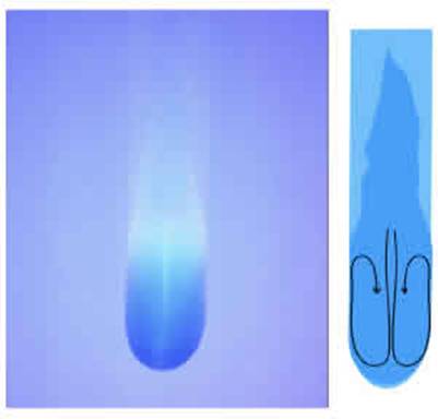
Figure 9: Water droplet - The three images are sep- arated by 1 s. The real size of the images is 20 mm width. On the left, a line of blue methyl was drawn. The droplet came from the top and crossed the line. On the side of the wake we can see that the blue coloring went upwards. The angle of inclination was 30 and the volume of the droplet 75 uL.
V Flow in the wake
As shown in Figs. 2b and 6, while moving on the frosted glass the water droplet releases some water in its wake. The lm is thick at rst, depending on the speed of the droplet 39. Then some liquid drains back towards the droplet but a thin lm remains. Fig. 8 shows a close-up of a sliding droplet (the droplet volume was 100 uL and the angle 35). The wake is about 1 cm wide. The droplet was colored using methylene blue. The wake can be seen more clearly in this picture. On the right, the picture was sketched over to enhance the contrast. The droplet, in dark blue, is rounded along the advancing contact line, while the rear looks like a ame. The liquid lm is presented in light blue. The shape of the droplet shows that a thick lm is released just after the passage of the droplet. This lm retracts towards the axis of symmetry that releases the thin lm.
To obtain information about the movement of the liquid in the wake, a line of methylene blue was drawn on the surface of the frosted glass (see image on the left in Fig. 9). When the line had dried the frosted glass was inclined at 30°; a droplet made of pure water with a volume of 75 uL was then placed on the glass. In the pictures in the middle and on the right the droplet had already crossed Figure 9: Water droplet - The three images are separated by 1 s. The real size of the images is 20 mm width. On the left, a line of blue methyl was drawn. The droplet came from the top and crossed the line. On the side of the wake we can see that the blue coloring went upwards. The angle of inclination was 30° and the volume of the droplet 75 uL. the line. We can see that the ow speed prole is not completely oriented downhill. The ow in the middle of the wake goes downhill, but at the side of the wake the ow goes upwards. In summary, the ow inside the droplet, close to the surface of the frosted glass, is represented by the arrows on the right of Fig. 8. The ow goes downwards in the middle of the droplet but upwards at the sides. Note that the ow is three dimensional; however, more information is needed for a complete picture of water flow.
In Fig. 8 (left) we can see a thin white line in the middle of the droplet. Actually, the blue color was disappearing: after 400 mm of travel, the droplet was nearly transparent. The methylene blue was adsorbed on the Saint-Gobain glass material. The company does not provide information on the composition of the glass, but whatever the reaction, this phenomenon clearly shows that a chemical or adsorption reaction may occur during movement of the droplet. The droplet also decolored on the smooth side, but to a lesser extent. This observation raises an interesting question regarding the purication or the chemical reaction that can be induced in a single droplet. The frosted glass allows close interaction between the surface and the droplet because (i) roughness increases the contact surface (r 1) and (ii) when the droplet slides along the surface, the thin lm interacts for a long time before draining back to the droplet. This technique could possibly be extended if we consider the frosted glass as a 2D trickle-bed reactor 40; that is, a vertical reactor that uses the motion of the liquid induced by gravity to ow through a granular material made of particles (3D) or through the channel network (frosted glass 2D) on the surface of which the liquid reacts. The frosted glass surface could be made functional by silanization or grafting 41.

Figure 10: Water droplet - (a) Typical dirt released after drawing on frosted glass. The liquid evaporates leaving dirt along the contact line. (b) Superimposition of 5 pictures obtained after the passage and complete evaporation of 5 successive droplets.

Figure 11: Water droplet - (a) After the passage of a droplet, a liquid lm is released on the frosted glass (in the picture on the left). After evaporation we can observe a thin trace due to the accumulation of dust (picture on the right). (b) Due to the pinning of the contact line, a micro-channel can be drawn between two droplets (1). The liquid can then ow from the smallest to the biggest droplet (2). The ow rate changes during the evaporation process. Picture 3 shows the result after complete evaporation of the droplet.
VI Perspectives
Besides the chemical or adsorption reactions that can be exploited, the high hysteresis characteristics of the surface are important. The passage of one droplet on the frosted glass may release some traces of dirt, as can be observed in our homes (Fig. 10a). Actually, the dust present in the room gets trapped on the surface of the frosted glass. The droplet collects it, and after evaporation two parallel lines can be seen that correspond to the boundaries of the liquid lm released by the droplet (Fig 11a). On complete evaporation these lines become invisible. If we breathe close to the surface, the two lines become visible. These lines may change the trajectory of another droplet. Successive droplets were released when the previous droplet had totally evaporated. The starting position was identical for all the droplets. In Fig. 10b, ve pictures of the wake of ve successive droplets are superimposed. The trajectories are no longer straight lines during the rst centimeters of motion. The droplet tends to move laterally to avoid" a previous trajectory. Because the contact angle of the frosted glass is pinned, it is also possible to draw a path with a simple feather pen. In Fig. 11b two droplets were joined using a pen. The width of the channel was about 1 mm and the length, 20 mm. The thickness Figure 11: Water droplet - (a) After the passage of a droplet, a liquid lm is released on the frosted glass (in the picture on the left). After evaporation we can observe a thin trace due to the accumulation of dust (picture on the right). (b) Due to the pinning of the contact line, a micro-channel can be drawn between two droplets (1). The liquid can then ow from the smallest to the biggest droplet (2). The ow rate changes during the evaporation process. Picture 3 shows the result after complete evaporation of the droplet. was less than two tenths of millimeter. As soon as the droplets were connected a ow was established from the smaller to the bigger droplet, due to the dierence in Laplace pressure (some blue coloring can be seen in the initial pure water droplet on the right). This very exible way of drawing microchannels resembles a system exploited by Walsh et al 9. However, in the case of frosted glass, the system is open and subject to evaporation. The bottom picture of Fig. 11b shows the result after complete evaporation, which limits the duration of the experiment and changes the balance of pressure between the droplets.
VII Conclusion
Frosted glass has been shown to be a very simple system with peculiar wetting properties when the plate is horizontal. For silicone oil, macroscopic spreading can be studied over a very long period using very simple instruments. The microscopic behaviour has yet to be discovered. The way the oil invades the complex network of crevices and hills could aid our understanding of the isotropic behaviour observed. Concerning the water droplet, the high contact angle hysteresis and the pinning of the contact line could be exploited to draw microchannels and trigger microow in this low-cost open micro uidic system.
On the inclined plate, the trajectory over a long distance of a droplet of oil and and one of water has been shown to follow a logarithmic law for the intermediate range of time (between 10 s after release and 2000 s). This behaviour was rationalised using a simple model that takes into account the dependence of the thickness of the wake on droplet speed.Droplet speed has been shown to decrease exponentially with distance from its origin. In both cases (water and oil), this decrease is due to the loss of mass of the liquid located at the advancing front. Lateral spreading is the main loss mechanism for the oil, while for water, loss on the surface and evaporation of the lm in the wake are the dominant eects.
Finally, we studied ow in the wake of the water droplet. The slow drainage and the large area of contact due to roughness lead to good interaction between the liquid and the solid. This property has been shown to cause discoloration of the methylene blue. Some perspectives of this work belong to domains for which a chemical reaction with a surface is needed. The ow in the network of channels of the frosted surface enables eficient contact between the solid and the liquid.
Acknowledgements
SD thanks the FNRS for nancial support as a senior research associate. This work was also support by PDR-31226867 WOLFLOW (F.R.S.-FNRS). The Author would like to warmly thank Pr. Denis Terwagne for fruitful discussions about this fascinating system and for his vision on potential biomimetic applications. The Author would like also to thank Pr. Nicolas Vandewalle for the use of GRASP laboratory equipment. Finally, SD thanks Mathieu, Chloe and Alice Dorbolo for revealing the remarkable properties of frosted glass.

